


Connecting to the Network
Matrix DFE-Gold Series Installation Guide 3-17
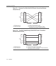
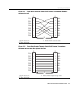
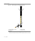
Figure 3‐10forfour‐wireRJ45connections.RefertoFigure 3‐11andFigure 3‐12
foreight‐wireRJ45connections.
e. EnsurethatthetwistedpairconnectionmeetsthedBlossandcablespecifications
outlinedintheCablingGuide.Referto“RelatedDocuments”onpage xivfor
informationonobtainingthis document.If
alinkisstillnotestablished,contact
EnterasysNetworks.Referto“GettingHelp”onpage 1‐8fordetails.
4. Repeatsteps1through3above,untilallconnectionshavebeenmade.
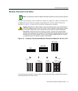
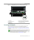
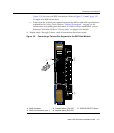
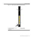
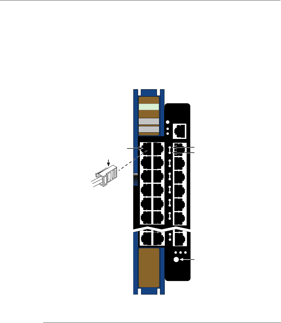
Figure 3-8 Connecting a Twisted Pair Segment to the DFE-Gold Module
1 RJ45 connector 3 Transmit status (TX) LED 5 GROUP SELECT button
2 RJ45 port connector (port 1) 4 Receive status (RX) LED
COM
OFFLINE/
RESET
GROUP 3
GROUP 1 GROUP 2
CPU
MGMT
1X
6X
4G4202-72
Gb ENET
Â
GROUP
123
GROUP
SELECT
24X
DFE
Ä
Ã
Á
À