


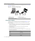


Connecting to the Network
3-24 Hardware Installation
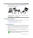
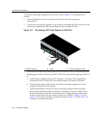
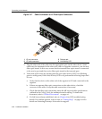
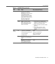
Figure 3-17 Cable Connection to LC Fiber-Optic Connectors
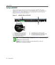
3. Plugtheotherendofthecableintotheappropriateportontheotherdevice.Some
cablesmaybeterminatedattheother endwithtwoseparateconnectors,oneforeach
fiber‐opticstrand.Inthiscase,ensurethatthetransmitfiber‐opticstrandisconnected
tothereceiveport
andthereceivefiber‐opticstrandtothetransmitport.
4. VerifythatalinkexistsbycheckingthattheportLink/ActivityLEDison(blinking
greenorsolidgreen).IftheLink/ActivityLEDisoff,performthefollowingstepsuntil
itison:
a. Verifythatthedeviceattheotherendof
thesegmentisONandconnectedtothe
segment.
b. Ifthereareseparatefiber‐opticconnectionsontheotherdevice,checkthe
crossoverofthecables.Swapthecableconnectionsifnecessary.
c. Checkthatthefiber‐opticconnectionmeetsthedBlossandcablespecifications
outlinedintheCablingGuidefor
multimodemodecabling.Toobtainthis
document,referto“RelatedDocuments”onpage xvi.
d. Ifalinkhasnotbeenestablished,refertoChapter 4forLEDtroubleshooting
details.Ifaproblempersists,refertoreferto“GettingHelp”onpage xviiifor
detailsoncontactingEnterasys Networksforsupport.
1 LC port connector 3 Release tab
2 LC cable connector 4 Link/Activity LED