


Preparing to Install into a Chassis
DFE-Platinum Series Hardware Installation Guide 3-11
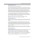
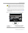
4. Slidethemoduleintotheslotuntilyoucanengagethetopandbottomlockinglevers.
5. RefertotheCautionnoteabove,thenrotatethetwoleversintotheclosedposition.
6. Ifthechassisinwhichthemoduleisinstalledwaspowereddownfortheinstallation,
turnthepowersupplieson.Check
toseethatthemoduleCPULEDsettlesatsolid
greenafterafewminutes.IftheLEDdoesnotturnsolidgreen,refertoChapter 4for
troubleshootingdetails.
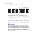
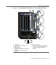
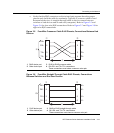
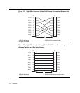
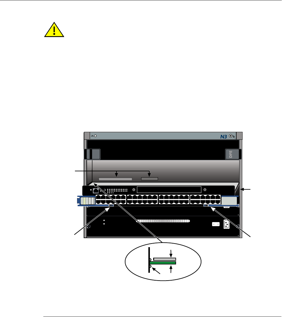
Figure 3-3 Installing Module into Matrix N3 or N5 Chassis (Matrix N3 shown)
Caution: In step 5, do not force the locking levers to the point that they touch the face of
the front panel. Forcing the locking levers to this point could damage the module and
chassis.
Precaución: En el paso 5, tenga cuidado de no llevar las palancas de cierre a un punto
en donde estén en contacto con el panel frontal. Si lo hace, podría dañar el módulo y/o el
chasis.
1 Card guides 5 Upper locking tab (shown in closed position)
2 Slot 1 (Top slot is slot 3.) 6 Lower locking tab (shown in closed position)
3 Module card 7 FTM2 and power backplane connectors
4 Metal back panel
7C203-1
REDUNDANCY
PWR
100-125V~12.0A
200-240V~6.0A
50/60 Hz
7C203-1
REDUNDANCY
PWR
100-125V~12.0A
200-240V~6.0A
50/60 Hz
1X
G
R
O
U
P
1
G
R
O
U
P
2
11X
13X
23X
OFFLINE/
RESET
COM
CPU
MGMT
GROUP
SELECT
GROUP
1
2
3
4
5
6
7
8
9
10
11
12
POE
12 X
14X
24X
G
R
O
U
P
3
25X
35X
26X
36X
G
R
O
U
P
4
37X
47X
38X
48X
DFE
7G4285-49
Gb ENET
1
2
3
4
Á
Æ
Ä
Å
Â
Ã
À