


Connecting to the Network
DFE-Platinum Series Hardware Installation Guide 3-13
Connecting UTP Cables to DFE Modules
ThefixedRJ45frontpanelconnectionsofthe7G4285‐49and7G4205‐72are10/100/
1000 Mbpsports.Theseportshaveinternalcrossovers,andsupportautomatic‐polarity
sensingwhenconfiguredforautomatic‐negotiation.
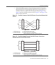
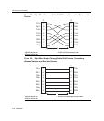
Ifautomatic‐negotiationisnotactivatedonaport,useastraight‐throughcablewhen
connectingaworkstationtothe
port.Whenconnectinganetworkingdevicetotheport,
suchasabridge,repeater,orrouter,useacrossovercable.
Ifaportissetforauto‐negotiation,automatic‐polaritysensingisalsoactivated.
Automatic‐polaritysensingeliminatestheneedforacrossovercable,regardlessifthe
connectionistoanother
networkdeviceoraworkstation.
TheRJ45fixedfrontpanelconnectorsofthe7G4285‐49and7G4205‐72alsosupport
PoE‐compliantconnectionstoPDs(powereddevices)thatrequire48Vdcthroughthe
UTPcabletooperate.Whenthe48VdcisavailablethroughthebackplaneofanN5
chassisor
externallyfromanN‐POEPowerSystem,youcanverifyifthereispowerat
eachportasdescribedlaterinthisprocedure.
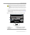
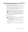
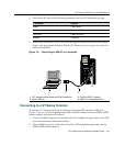
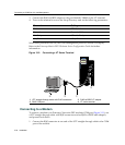
Making the UTP Connections
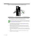
ToconnectandverifyUTPcableconnectionstoRJ45ports(1through48or72),referto
Figure 3‐4andproceedasfollows:
1. EnsurethatthedeviceconnectedtotheotherendofthesegmentispoweredON.
2. InserttheRJ45connectoronthetwistedpairsegmentintotheappropriateRJ45port
connector.
Note: All RJ45 front panel ports on these DFE modules support Category 5 Unshielded
Twisted Pair (UTP) cabling with an impedance between 85 and 111 ohms. Category 3
cable may be used if the connection is going to be used only for 10 Mbps.
Caution: To prevent damage to the equipment, do not connect the PoE supported ports
(1 through 48 or 72) to segments running between buildings. Keep connections to
equipment within the building.
Precaución: Para evitar que el equipo se dañe, no conecte los puertos PoE
(1 a 48 o 72) a segmentos que vayan de un edificio a otro. Mantenga las conexiones de
los equipos dentro del edificio.