


Index-2
Module coverplate
removal of B-7
Module features 1-2, 1-4
N
NEM B-12
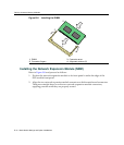
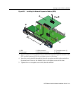
installing 1-6
Network
connecting to 3-12
Network Expansion Module 1-6
Network expansion module
installation of B-12
Network Requirements
list of 2-1
O
Offline/reset switch
use of 4-11
Optional network expansion module
installation of 3-3
P
Pinout assignments
console port A-4
Pinouts
crossover 3-15, 3-16
straight-through 3-15, 3-16
PoE (Power over Ethernet)
overview of C-1
PoE operation
power connection for 3-12
PoE port status, viewing of 4-4
R
Receive LEDs
viewing of 4-2, 4-4
Regulatory Compliance A-4
Related manuals, obtaining xvi
Required tools 3-2, B-1
S
Safety requirements A-4
Specifications A-1
7G4205-72 A-3
7G4285-49 A-2
Standards compatibility 1-7
T
Transmit LEDs
viewing of 4-2, 4-4
Troubleshooting 4-1
checklist for 4-8
U
Unpacking the module 3-2
User Personalized Networks (UPN) See Secure
Networks Policy Support.
UTP cable connections
front panel 3-13
V
Viewing Receive and Transmit Activity
instructions for 4-2, 4-4
W
WebView
introduction to 1-6