


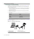

Connecting to the Network
3-26 Hardware Installation
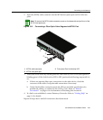
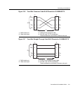
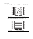
Connecting Fiber-Optic Cables to MT-RJ Mini-GBIC Ports
Thissectioncontainstheproceduresforconnectinga1000BASE‐SXmultimodefiber‐optic
segmentfromthenetworkorotherdevicetoanMT‐RJportconnectorinaMini‐GBIC
(MGBIC‐MT01).
Eachfiber‐opticlinkconsistsoftwofiber‐opticstrandswithinthecable:
•Transmit(TX)
• Receive(RX)
Thetransmitstrandfrom
theMT‐RJportconnectstothereceiveportofafiber‐optic
GigabitEthernetdeviceattheotherendofthesegment.Thereceivestrandofthe
applicableMT‐RJportconnectstothetransmitportofthefiber‐opticGigabitEthernet
switch.
Enterasys Networksrecommendslabelingfiber‐opticcablesto
indicatereceiveand
transmitends.Manycablesarepre‐labeled,providingmatchinglabelsortapesatboth
endsofeachstrandofcable.
ToconnectanMT‐RJcabletoafixedMT‐RJconnectorofaMini‐GBIC:
1. RemovetheprotectivecoversfromtheMini‐GBICMT‐RJfiber‐optic
portandfrom
theconnectorsoneachendofthecable.
Warning: Fiber-optic Mini-GBICs use Class 1 lasers. Do not use optical instruments to
view the laser output. The use of optical instruments to view laser output increases eye
hazard. When viewing the output optical port, power must be removed from the network
adapter.
Advertencia: Los Mini-GBICS de fibra optica usan lasers de clase 1. No se debe usar
instrumentos opticos para ver la potencia laser. El uso de los instrumentos opticos para
ver la potencia laser incrementa el riesgo a los ojos. Cuando vean el puerto de la potencia
optica, la corriente debe ser removida del adaptador de la red.
Warnhinweis: Mini-GBICs mit Fiber-Optik Technologie benutzen Laser der Klasse 1.
Benutzen sie keinesfalls optische Hilfsmittel, um die Funktion des Lasers zu überprüfen.
Solche Hilfsmittel erhöhen die Gefahr von Sehschäden. Wenn sie den optischen Port
überprüfen möchten stellen Sie sicher, dass die Komponente von der
Spannungsversorgung getrennt ist.
Note: Leave the protective covers in place when the connectors are not in use to prevent
contamination.