


Rack Mounting the Switch
3-6 Hardware Installation
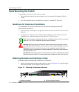
Rack Mounting the Switch
Toinstalltheswitch ina19‐inchrack,youneed:
•Tworackmountbracketsandmountingscrews(rackmountkit)shippedwiththe
switch.
•Fouruser‐suppliedscrewstoattachtheswitchtoastandard19‐inchrack.
Guidelines for Rackmount Installation
Theinstallationsitemustbewithinreachofthenetworkcablingandmeetthe
requirementslistedbelow:
• Appropriategroundedpowerreceptaclesmustbelocatedwithin152cm(5ft)ofthe
location.
•Atemperatureofbetween0°C(32°F)and40°C(104°F)mustbemaintainedatthe
installationsite
withfluctuationsoflessthan10°C(18°F)perhour.
Attaching Brackets and Installing in Rack
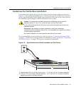
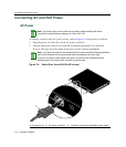
Proceedasfollowstoinstalltheswitchintoa19‐inchrack:
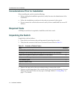
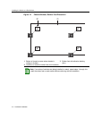
1. Attachtherackmountbracketstotheswitch,asshowninFigure 3‐3,usingtheeight
M3x6mmflatheadscrewsshippedwiththeswitch.
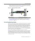
Figure 3-3 Attaching the Rackmount Brackets
Note: To ensure proper ventilation and prevent overheating, leave a minimum clearance
space of 5.1 cm (2.0 in.) at the left, right, and rear of the switch.
Warning: Before rack-mounting the switch, ensure that the rack can support it without
compromising stability. Otherwise, personal injury and/or equipment damage may result.
Advertencia: Antes de montar el equipo en el rack, asegurarse que el rack puede
soportar su peso sin comprometer su propia estabilidad, de otra forma, daño personal o
del equipo puede ocurrir.
Warnhinweis: Überzeugen Sie sich vor dem Einbau des Gerätes in das Rack von dessen
Stabilität, ansonsten könnten Personenschäden oder Schäden am Gerät die Folge sein.
1 Rackmount brackets 2 M3x6 mm flathead screws
Á
À
Á
À
1
2
11
12
13
14
23
24
Console
25
26
27
28
25/Up 26/Down
Stack
27
28
1357911131517192123
2 4 6 8 1012 14 16 18 20 2224
CPU
RPS
MGR
A2H124-24P
123456789101112 131415161718192021222324