


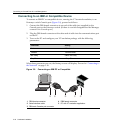


Connecting to the Network
3-20 Hardware Installation
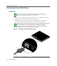
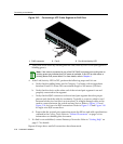
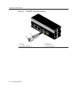
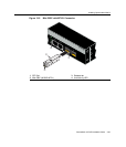
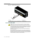
Figure 3-12 Connecting a UTP Cable Segment to RJ45 Port
3. VerifythatalinkexistsbycheckingthattheLink/ActivityLEDisON(solidgreenor
blinkinggreen).
4. IftheLink/ActivityLEDisOFF,performthefollowingstepsuntilitison:
a. VerifythatthecablingbeingusedisCategory 5orbetterwithanimpedance
between85and111 ohmswitha
maximumlengthof100meters(328feet).
b. Verifythatthedeviceattheotherendofthetwistedpairsegmentisonand
properlyconnectedtothesegment.
c. VerifythattheRJ45connectorsonthetwistedpairsegment havetheproper
pinoutsandcheckthecableforcontinuity.Typically ,acrossover
cableisused
betweenhubdevicesbutthisisnotnecessary.Astraight‐throughcablecanbe
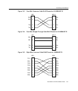
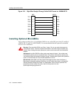
usedtoconnectbetweentheswitchandanydevice.RefertoFigure 3‐13and
Figure 3‐14forfour‐wireRJ45connections.RefertoFigure 3‐15andFigure 3‐16
foreight‐wireRJ45connections.
d. Ensure
thatthetwistedpairconnectionmeetsthedBlossandcablespecifications
outlinedintheCablingGuide.Referto“RelatedDocuments”onpage xvifor
informationonobtainingthis document.
5. Ifalinkisnotestablished,contactEnterasys Networks.Referto“GettingHelp”on
page 1‐7fordetails.
Repeatallsteps
aboveuntilallconnectionshavebeenmade.
1 RJ45 connector 2 Port 8 3 Port 8 Link/Activity LED
Note: If the cable is connected to one of the PoE RJ45 front panel ports, solid green or
blinking green also indicates that PoE power is available. If the LED is solid amber or
blinking amber PoE power failed. For more details, refer to Chapter 4.
1
2
11
12
1357911 13 1517192123
24681012 14 16 18 20 2224
1234567891011 12
À
Á
Â