


Connecting AC and RPS-SYS Power
3-16 Hardware Installation
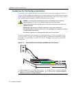
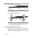
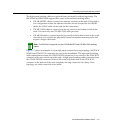
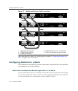
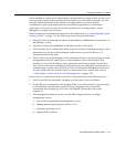
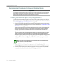
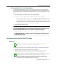
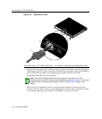
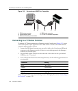
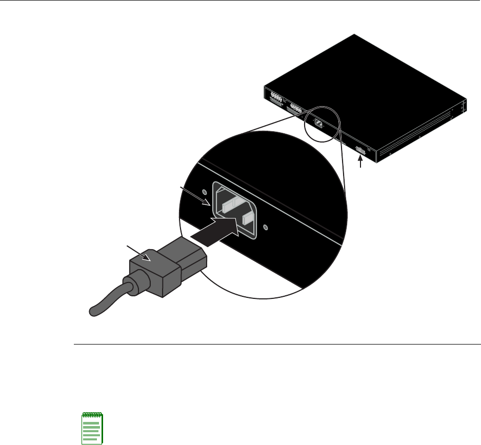
Figure 3-8 Switch Rear View
3. ObservethatthepowerCPULED(notshown),locatedonthefrontpanel.Duringthe
initialization,theCPULEDwillstartbyilluminatingsolidamber,thenstartblinking
green,thenblinkingamber,thenblinkinggreenagainuntiltheendofthe
initialization,andthenturnssolidgreen.
Iftheswitch
isastandaloneswitch,itwilltakeapproximately30 secondsforthe
switchtostartup.IftheswitchisastackManager,itcantakeupto3minutesormore
tostartup,depe ndingonthenumberofMemberswitchesinthestack.
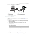
1 AC power cord 2 AC power connector 3 Connector for external redundant power supply
Note: If the CPU LED illuminates solid red, there was a critical failure. For more
information about the LED indications and troubleshooting, refer to Chapter 4. If you need
additional help, contact Enterasys Networks. Refer to “Getting Help” on page 1-8 for
details
.
Redundant Power Supply
AC LINE
100-240 VAC
50-60 Hz
0.8 A MAX
MAC ADDRESS
SERIAL NO.
STACK UP
STACK DOW
N
AC LINE
100-240 VAC
50-60 Hz
0.8 A MAX
À
Á
Â