


Connecting to the Network
3-30 Hardware Installation
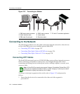
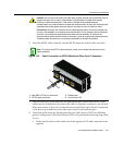
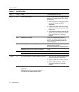
Figure 3-19 Cable Connection to LC Fiber-Optic Connectors
3. Plugtheotherendofthecableintotheappropriateportontheotherdevice.Some
cablesmaybeterminatedattheotherendwithtwoseparateconnectors,oneforeach
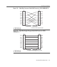
fiber‐opticstrand.Inthiscase,ensurethatthetransmitfiber‐opticstrandisconnected
tothereceiveport
andthereceivefiber‐opticstrandtothetransmitport.
4. VerifythatalinkexistsbycheckingthattheportLink/ActivityLEDison(blinking
greenorsolidgreen).IftheLink/ActivityLEDisoff,performthefollowingstepsuntil
itison:
a. Verifythatthedeviceattheotherendof
thesegmentisONandconnectedtothe
segment.
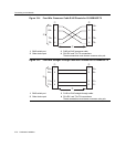
b. Ifthereareseparatefiber‐opticconnectionsontheotherdevice,checkthe
crossoverofthecables.Swapthe cableconnectionsifnecessary.
c. Checkthatthefiber‐opticconnectionmeetsthedBlossandcablespecifications
outlinedintheCablingGuidefor
multimodemodecabling.Toobtainthis
document,referto“RelatedDocuments”onpage xvi.
d. Ifalinkhasnotbeenestablished,refertoChapter 4forLEDtroubleshooting
details.Ifaproblempersists,refertoreferto“GettingHelp”onpage 1‐8for
detailsoncontactingEnterasys Networksforsupport.
5. Repeatsteps
1through4,above,untilallconnectionshavebeenmade.
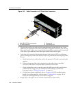
1 Mini-GBIC MT-RJ port connector 3 Release tab
2 LC cable connector 4 Link/Activity LED
21
22
23
24
21
22
23
24
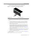
B2G124-24
À
Â
Á
Ã