Hardware Installation
2-5
6. Observe the Self Test – When you power on the access
point, verify that the Power indicator stops blinking and
remains on green, and that the other indicators start
functioning as described under “LED Indicators” on page 1-4.
If the Power LED does not stop blinking or turns on yellow,
the self test has not completed correctly. Refer to the
RoamAbout Mobility System Software Configuration Guide
for troubleshooting information.
7. Position the Antennas – Each antenna emits a radiation
pattern that is a toroidal sphere (doughnut shaped), with the
coverage extending most in the direction perpendicular to the
antenna. Therefore, the antennas should be oriented so that
the radio coverage pattern fills the intended horizontal space.
Also, the diversity antennas should both be positioned along
the same axes, providing the same coverage area. For
example, if the access point is mounted on a horizontal
surface, both antennas should be positioned pointing
vertically up to provide optimum coverage.
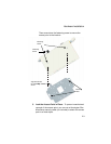
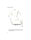
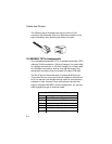
If you choose to use the supplied bezel, position the bezel directly
over the access point so that the LED holes line up with the LEDs
on the unit and snap the bezel into place, as shown in the
following figure:


