


33
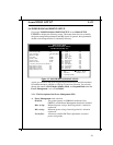
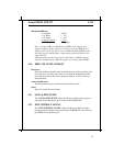
3-6 INTEGRATED PERIPHERALS
Award BIOS SETUP 3-14
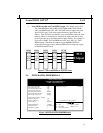
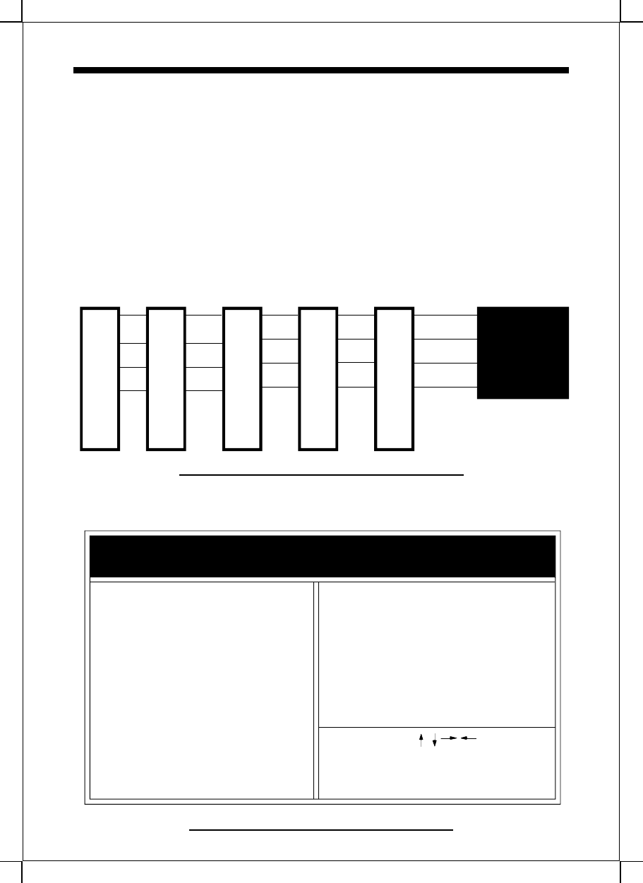
ROM PCI/ISA BIOS
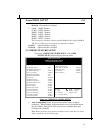
INTEGRATED PERIPHERALS
WARD SOFTWARE, INC.
IDE HDD Block Mode : Enabled USB Controller : Disabled
IDE Primary Master PIO : Auto USB Keyboard Support * : Disabled
IDE Primary Slave PIO : Auto
IDE Secondary Master PIO : Auto
IDE Secondary Slave PIO : Auto
Onboard Primary PCI IDE : Enabled
Onboard Secondary PCI IDE : Enabled
PCI Slot IDE 2nd Channel : Enabled
Onboard FDC Controller : Enabled
Onboard UART Port 1 : Auto
Onboard UART Port 2 : Auto * Only visible when USB is Enabled
UART 2 Mode : Standard
Onboard Parallel Port : 378/IRQ7
Parallel Port Mode : ECP+EPP1.9
ECP Mode Use DMA : 3
Esc : Quit : Select Item
F1 : Help PU/PD/+/- : Modify
F5 : Old Values (Shift)F2 : Color
F7 : Load Setup Defaults
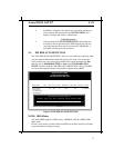
• Used MEM base addr and Used MEM Length: The default value is N/A.
The Used MEM base addr (CB00, CC00, D000, D400, D800, DC00)
and Used MEM Length (8K, 16K, 32K, 64K) were to support the some
specific ISA Legacy cards with requested memory space below 1M
address. Now with these two funtions, users canm define where the used
memory address is located and its length of the legacy area that is used
by the legacy device to avoid the memory space conflict. For example, if
users select “D000” for Used MEM base addr” and “16K” for “Used
MEM Length”, that means the address region D000H-D3FFFH is
occupied by ISA legacy cards, and thus BIOS will not assign this region
for PnP/ISA and PCI cards.
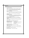
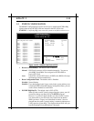
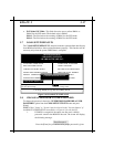
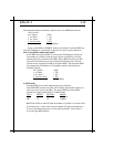
PCI
Chipset
INTA
INTD
PCI#1
PCI#2PCI#3
INTA
INTD
INTD
INTCINTB
INTC
INTB
INTBINTAINTD
INTC
INTCINTB
INTA
PCI#4
INTA
INTB
INTC
INTD
Figure 3-7 The Combination of PCI INT# lines
Figure 3-8 INTEGRATED PERIPHERALS
PCI#5
INTA
INTB
INTC
INTD