


InstallationKP6-LA
Page 3-7
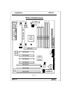
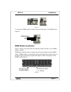
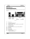
Figure 3
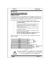
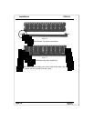
To remove the SIMM module: release the clips on both sides of the SIMM socket
(figure 4).
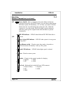
Figure 4
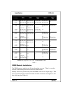
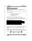
DIMM Module Installation
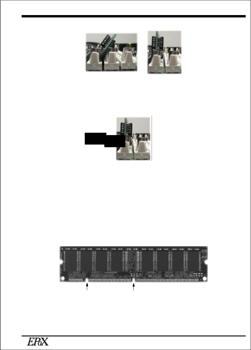
Figure 5 displays the notch marks and what they should look like on your DIMM
memory module.
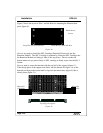
DIMMs have 168-pins and two notches that will match with the onboard DIMM
socket. DIMM modules are installed by placing the chip firmly into the socket at a
90 degree angle and pressing straight down (figure 6) until it fits tightly into the
DIMM socket (figure 7).
Figure 5
SIMM Release
Clip
CENTER KEY ZONE
(3.3 V DRAM)
LEFT KEY ZONE
(UNBUFFERED)