


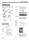

EPL-6000 LASER PRINTER
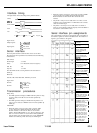
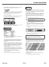
Interface timing
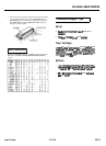
The figure below shows the timing for the parallel interface.
SELECT
-A
DATA’-a
4
DATA STROBE
ke.T
‘“i
BUSY
ACK
A: 1
ps
(min.) 8: 1 )B (min.)
C: 1 ps (min.)
D: approx. 6 ps
Signal levels
Output signals:
Input signals:
Vo,=Oto0.4V
v,,
= 2.4 to 5.0 V
v,,
=0 to 0.8 V
V,”
= 2.0 to 5.0 V
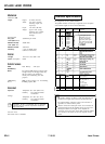
Serial interface
The laser printers built-in serial interface can be set for either
RS-232C or RS-422A operation. These interfaces have the following
characteristics.
Data format
Word length:
7 or 8 bits
Parity:
0 or 1 bit (None, Odd, Even, Ignore)
Start bits:
1 bit
Stop bits:
1 or 2 bits
The data format can be set using functions and menu items in
SelecType.
Baud rate
300, 600, 1200, 2400, 4800, 9600, 19200 bits per second.
Signal level
RS-232C:
RS-422A:
v,
= 2.2 to 12 V
v,
=-I.4
to -12V
v,
= 2.5 to 5V
v,
= 0 to 0.5 V
Transmission procedures
Ready/ Busy:
l
The DTR signal level changes to HIGH when the printer is ready
to receive data (or to LOW if set for inverted operation by
SelecType).
l
The DTR signal level changes to LOW when the printer is not
ready to receive data (or to HIGH if set for inverted operation by
SelecType).
XON/XOFF:
l
When the printer is ready to receive data, it sends an XON
(11 hex) to the host computer through the TD line for the
RS-232C interface or SD+ and SD- lines for the RS-422A
interface. When ROBUST-XON is set to ON (by SelecType). and
data is not received within one second of the XON signal being
sent, the printer sends an XON signal every second. If ROBUST-
XON is set to OFF, the printer sends only one XON signal.
l
When the printer is not ready to receive data, it sends an XOFF
(13 hex) to the host computer through the TD line for the
RS232C interface or SD+ and SD- lines for the RS-422A
interface.
l
The printer is ready to receive data when it is on line, no error
conditions exist, and the buffer is not tilled above the overload
value set with SelecType.
l
The printer is not ready to receive data when it is off line or
when it is on line but the remaining capacity of the data buffer is
less than the overload buffer value.
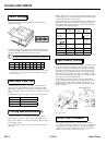
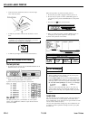
Serial interface pin assignments
The serial interface connector pm assignments and a description of
the interface signals are shown in the table below. The direction of
signals is given relative to the printer.
I
Description
Frame ground. Safety
I
ground Iine.
Transmit data
This pin transmits serial
data from the printer to
the computer.
I
Receive data.
This pin transmits serial
data from me computer to
Request to send. This pin
is HIGH when power is on
Clear to send. This pin
1
indicates that the computer
is
ready
to receive data
from the printer.
Data set ready. This pin
indicates mat the
computer
is ready to communicate
Signal ground. This pin
provides a ground for all the
signal lines.
-1
Send data. This
pin sends serial data from
the printer to the computer.
Signal level is RS-422A
,
/
Send data. This
pin sends serial
data from me printer to
the computer. Signal level
is RS-422A
Same as DTR.
I
Receive data. This
pin
transmits serial data from
j
the
computer to the printer
Signal Ievel is RS-422A.
Data terminal ready. This
pin indicates whether or not i
the printer is
ready to
;
receive data. If the printer
I
ready protocol is not
/
selected, this pin is always
,
HIGH
(i.e. the printer
is
1
ready to receive data). If
printer ready protocol is
selected, the printer can
/
accept data when the pin
level is HIGH. and cannot
accept data when the pin
:
level is LOW. When busy
i
Not a signal, but a +5V
1
power supply output.
Maximum of 300mA
i
/
Laser Printers
7/18/89
EPL-3