


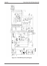
A.1.1 Connector Summary
This section describes the connector summary. The table A-1 lists the connoctor summary for every
connectors on the C199 main and the C160 power supply board. Also, the table A-2 to table A-10 lists the
detail signals for every connectors.
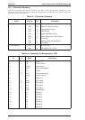
Table A-1. Connector Summary
Board Location Pin Description
C199 MAIN CN1 36 Centronics I/F
CN2 36 Serial I/Fn (Not Connected)
CN3 4 Carriage Motor Control
CN4 19 Head Control
CN5 4 Paper Feed Motor Control
CN6 5 Power Supply from C160 PS board
CN7 2 PE Sensor
CN8 3 Carriage Home Position Sensor
CN9 2 ASF sensor
C160 PSB/PSE CN1 2 AC inlet (L/N)
CN2 8 DC output (+5 V / +35 V)
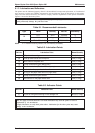
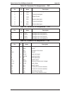
Table A-2. Connector Pin Assignments - CN1
Pin I/O Name Description
1 — GND Ground
2 — FG Frame Ground
3 LOGH Logic Hights
4 I -AFXT Auto line feed signal
5 — +5V +5VDC
6 O SLCT Printer select signal
7 I -SLIN Select in signal
8 PE Paper end
9 O -ERR Error signal
10 O BUSY Busy signal
11 I -INIT INIT signal
12 O -ACK ACK signal
13 I -STB Strobe signal
14 D7 Data bit 7
15 D0 Data bit 0
16 D6 Data bit 6
17 D1 Data bit 1
18 D5 Data bit 5
19 D2 Data bit 2
20 D4 Data bit 4
Appendix Epson Stylus Color 200/ Epson Stylus 200
A-2 Rev. A