


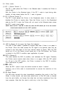
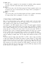
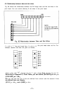
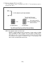
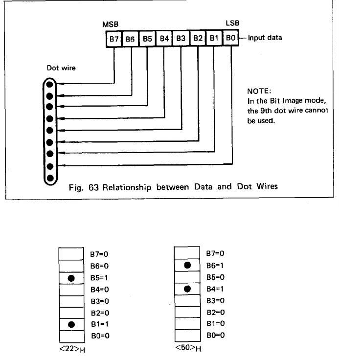
4.3. Relationship between data and dot wires
Fig. 68 shows the relationship between the Bit Image data and the dot wires in the
print head. You can control arbitrary 8 dot wires in the print head.
If a bit is “1,"
the print head fires. If a bit is “0,”
the print head does not fire. For
example, assume that data are given as follows;
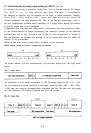
where a box with “•” denotes the bit “1” and a blank box denotes the bit “0.”
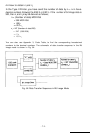
According to Appendix 3, Code Table, you can define (00100010)
2
as <22>
H
and
(01010000)
2
as <50>
H
.
As you can see the first 4 bits are defined from column and the second 4 bits
are defined from row. Namely,
(0101)
2
= <5>
H
, and (0600)
2
= <O>
H
.
-71-