


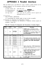
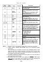


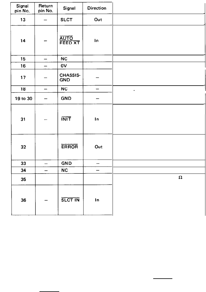
Table A2-1 (cont’d)
Description
This signal indicates that the printer is in
the selected state.
With this signal being at “LOW” level, the
paper is automatically fed one line after
printing.
(The signal level can be fixed to “LOW’
with DIP SW pin 2-3 provided on the
control circuit board.)
Not used.
Logic GND
level.
Printer chassis GND.
In the printer, the chassis GND and the
logic GND are isolated from each other.
Not used.
TWISTED-PAIR RETURN signal GND
level.
When the level of this signal becomes
“LOW’, the printer controller is reset to
its initial state and the print buffer is
cleared. This signal is normally at “HIGH”
level, and its pulse width must be more
than 50µs at the receiving terminal.
The level of this signal becomes “LOW’
when the printer is in -
1. PAPER END state
2. OFF-LINE state
3. Error state
Same as with Pin Nos. 19 to 30.
Not used.
Pulled UP to +5V through 3.3k
resistance.
Data entry to the printer is possible only
when the level of this signal is “LOW’.
(Internal fixing can be carried out with
DIP SW pin I-B. The condition at the
time of shipment is set “LOW’ for this
signal.)
NOTES: 1. “Direction” refers to the direction of signal flow as viewed from the printer.
2.
“Return” denotes “TWISTED PAIR RETURN” and is to be connected at signal
ground level.
As to the wiring for the interface, be sure to use a twisted-pair cable for each
signal and never fail to complete connection on the Return side. To prevent noise
effectively, these cables should be shielded and connected to the chassis of the
host computer and the printer, respectively.
3. All interface conditions are based on TTL level. Both the rise and fall times of
each signal must be less than 0.2µs.
4. Data transfer must not be carried out by ignoring the ACKNLG or BUSY signal.
(Data transfer to this printer can be carried out only after confirming the
ACKNLG signal or when the level of the BUSY signal is ”LOW”.)
-88-