


Stylus Photo R300/R310 Revision A
DISASSEMBLY AND ASSEMBLY Disassembly 47
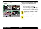
External View
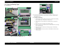
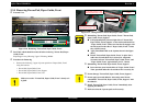
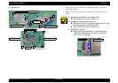
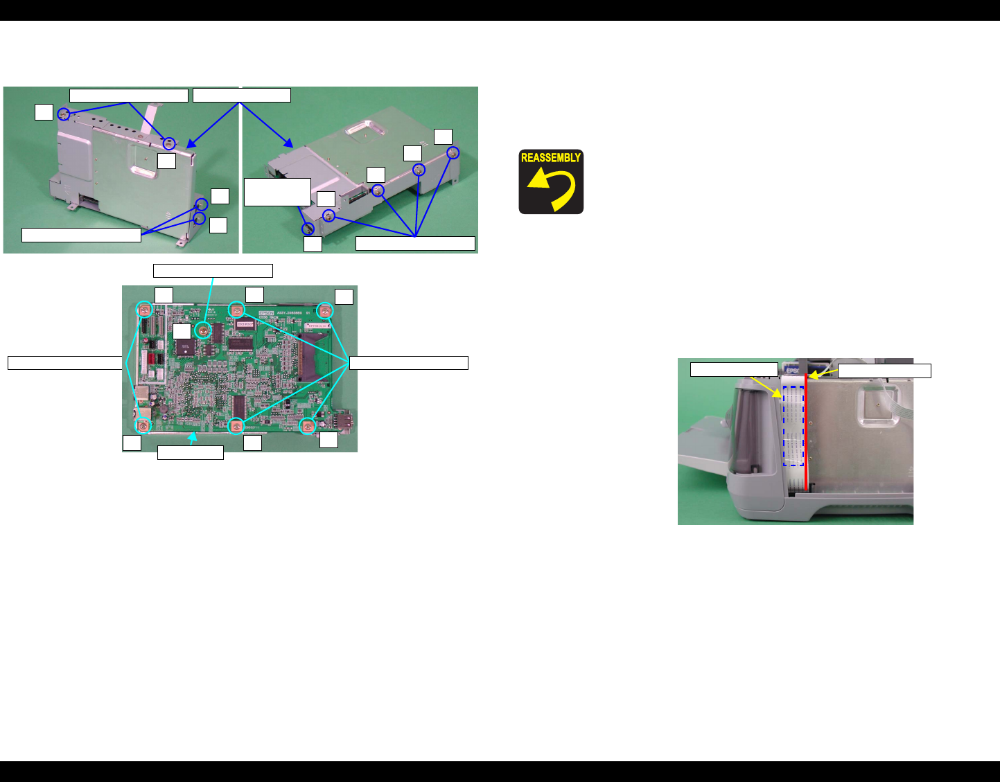
Figure 2-16. Removing "Main Board" (2)
7. Remove the screws (x9) which secure "Shield Plate, M/B". Then, remove
"Shield Plate, M/B".
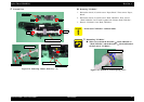
8. Remove the screws (x7) which secure "Main Board". Then, remove "Main
Board".
1
2
8
9
C.B.S 3x4 (4-6kgf•cm)
C.P. 3x4 (3-5kgf•cm)
C.B.S 3x6 (4-6kgf•cm)
3
4
5
6
7
C.B.S 3x4 (4-6kgf•cm)
C.P. 2.5x6
(3-5kgf•cm)
Shield Plate, M/B
1
2
3
4
5
6
7
C.B.S 3x6 (4-6kgf•cm)
C.B.S 3x10 (4-6kgf•cm)
Main Board
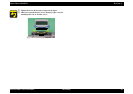
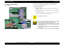
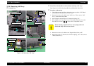
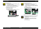
Reinstalling "Main Board"/"Shield Plate, M/B"
Screw in the order as shown in Figure 2-16.
Reinstalling "Housing, Support Slot Assy."
Match the dowels (x2) of "Housing, Support Slot Assy." and
the positioning holes of Shield Plate, M/B".
Screw in the order as shown in Figure 2-15.
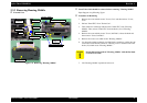
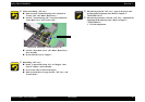
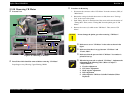
Reinstalling "Panel FFC"
Make sure to match "Panel FFC" and the lateral face of
"Shield Plate, M/B" and then attach it to "Main Board
Assy." with a two-sided tape.
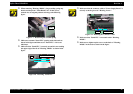
Figure 2-17. Mounting "Panel FFC"
Two-sided Tape
Positioning Point