


Stylus Photo R300/R310 Revision A
DISASSEMBLY AND ASSEMBLY Disassembly 59
External View
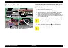
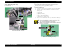
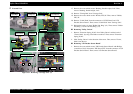
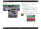
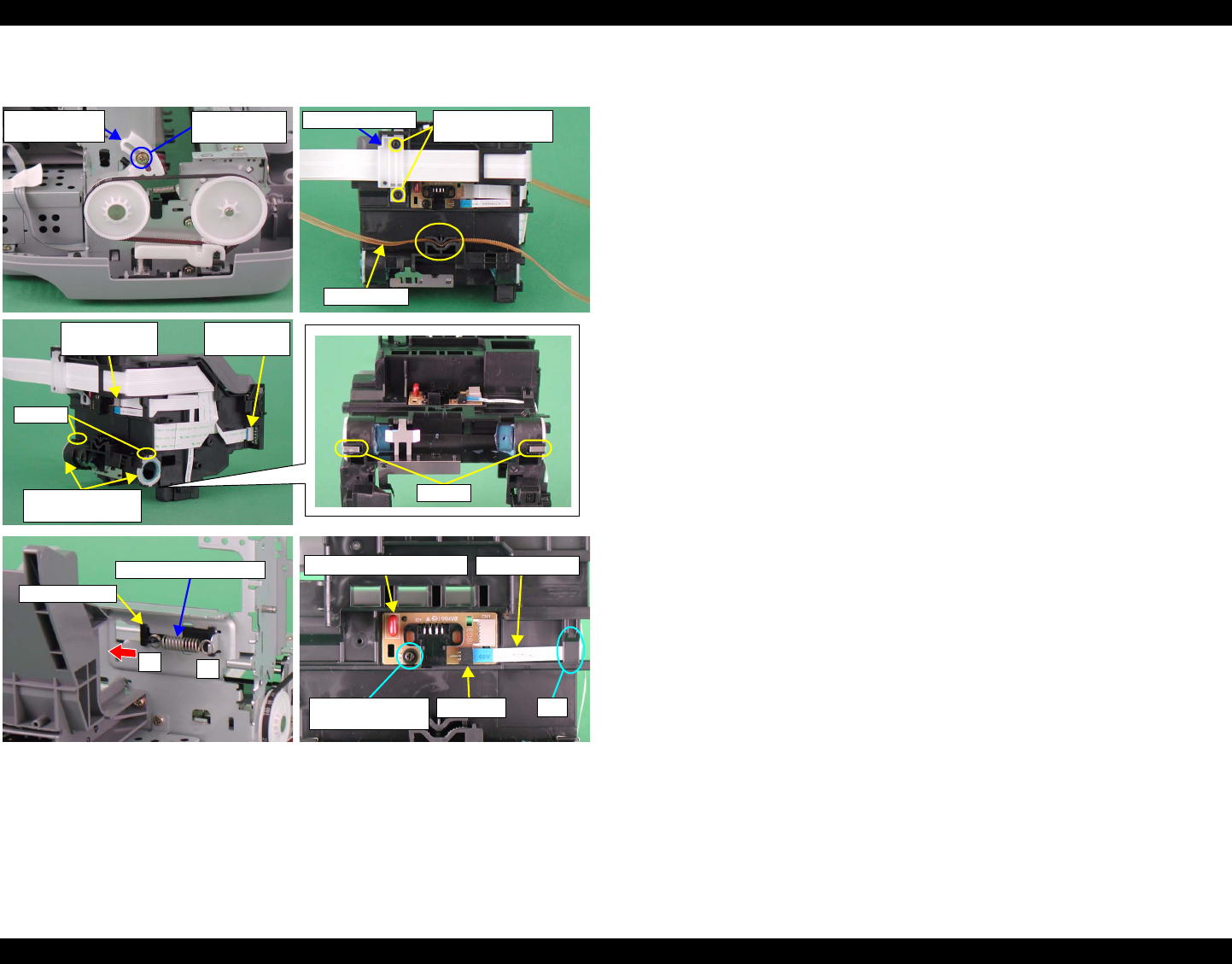
Figure 2-31. Removing "Carriage Unit" (3)
17. Remove the screw which secures "Bushing, Parallel Adjust, Left". Then,
remove "Bushing, Parallel Adjust, Left".
18. Remove "Timing Belt" from "Carriage Unit".
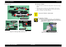
19. Remove the screws which secure "Holder, FFC; B". Then, remove "Holder,
FFC; B".
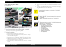
20. Remove "Cable, Head" from the connectors of "CSIC Board" and "CR
Encoder Sensor Board". Then, remove "Cable Head" from "Carriage Unit".
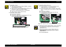
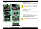
21. Release the hooks (x2) from "Holder Pad, Ring" (x2). Then, remove "Holder
Pad, Ring" (x2) and "Oil Pad, Ring" (x2).
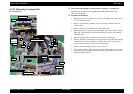
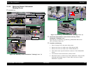
Removing "Pulley, Driven"
1. Remove "Extension Spring, 26.46" from "Pulley Driven" and the hook of
"Frame, Main" by using a flat-blade screwdriver. Then, remove "Extension
Spring, 26.46".
2. Slide "Pulley, Driven" in the direction of the arrow. Then, remove "Frame,
Main" from the slot.
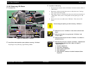
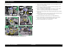
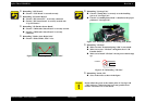
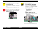
Removing "CR Encoder Sensor Board"
1. Remove the screw which secures "CR Encoder Sensor Board" with Phillips
screwdriver (No.0). Disconnect "PW Sensor FFC" from the connector of "CR
Encoder Sensor Board". Then, remove "CR Encoder Sensor Board".
Bushing, Parallel
Adjust, Right
C.P.S (P4) 3x6
(6-8kgf•cm)
Timing Belt
Holder, FFC ; B
C.P.B (P1) 1.7x5
(1.5-2.5kgf•cm)
CSIC Board
Connector
CR Encoder
Sensor Board
Holder Pad, Ring
Oil Pad, Ring
Hooks
Hooks
1
2
Pulley, Driven
Extension Spring, 26.46
CR Encoder Sensor Board
PW Sensor FFC
C.P.B (P1) 1.7x5
(1.5-2.5kgf•cm)
Connector
Slot