


RX
-
8581
SA
/
JE
/
NB
Page - 14 MQ372-02
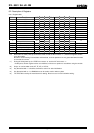
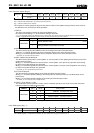
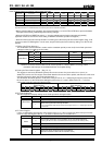
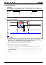
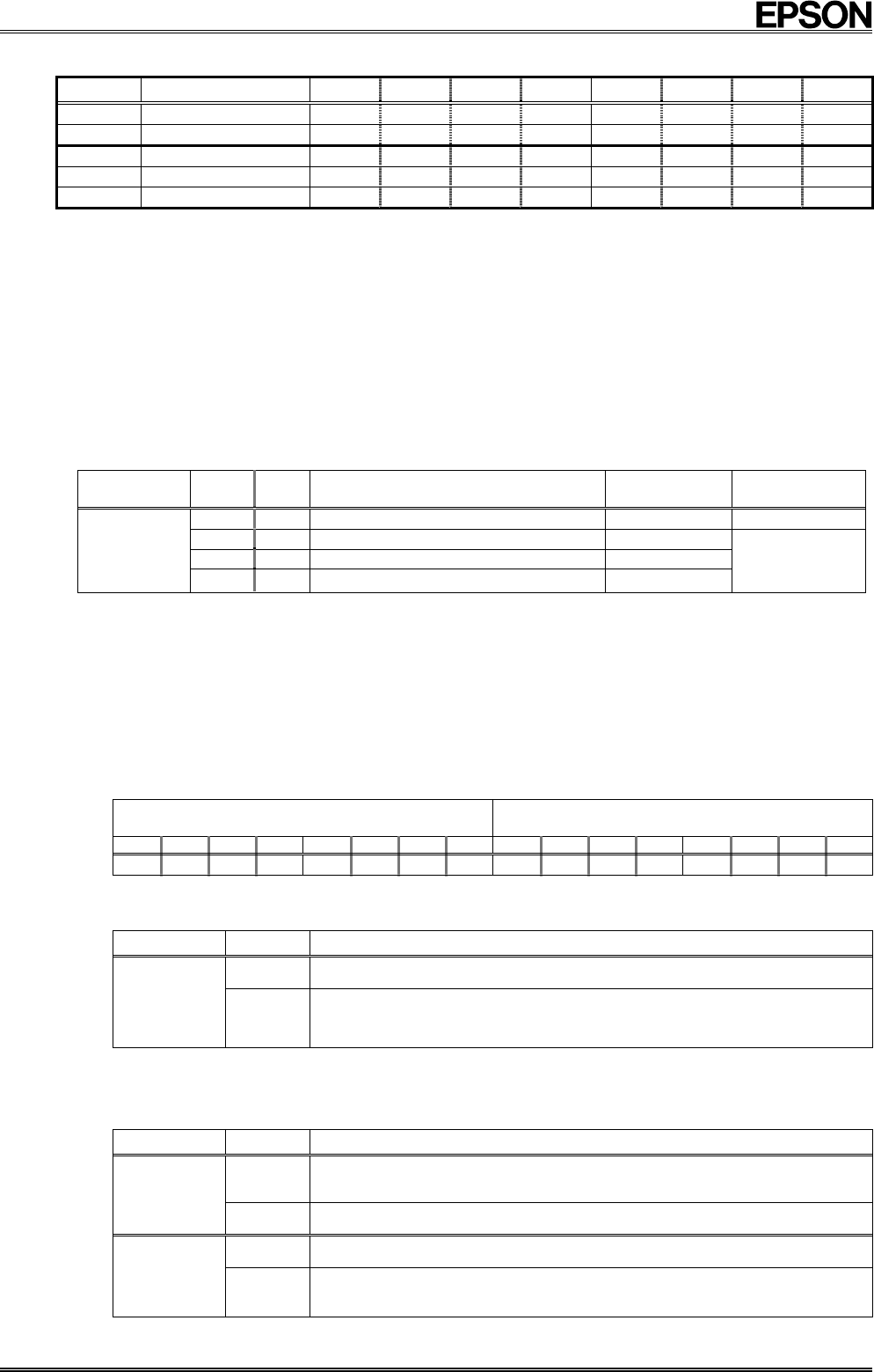
8.3.2. Related registers for function of time update interrupts.
Address Function bit 7 bit 6 bit 5 bit 4 bit 3 bit 2 bit 1 bit 0
B Timer Counter 0
128 64 32 16 8 4 2 1
C Timer Counter 1
•
•
•
•
2048 1024 512 256
D Extension Register
TEST WADA
USEL
TE
! !
TSEL1 TSEL0
E Flag Register
! !
UF
TF
AF
!
VLF
!
F Control Register
! !
UIE
TIE
AIE
!
STOP RESET
∗1)
"o" indicates write-protected bits. A zero is always read from these bits.
∗2)
Bits marked with "•" are RAM bits that can contain any value and are read/write-accessible.
∗ Before entering settings for operations, we recommend writing a "0" to the TE and TIE bits to prevent hardware
interrupts from occurring inadvertently while entering settings.
∗ When the STOP bit or RESET bit value is "1" the time update interrupt function operates only partially.
(Operation continues if the source clock setting is 4096 Hz. Otherwise, operation is stopped.)
∗ When the fixed-cycle timer interrupt function is not being used, the fixed-cycle timer control register (Reg – B to
C) can be used as a RAM register. In such cases, stop the fixed-cycle timer function by writing "0" to the TE and
TIE bits.
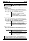
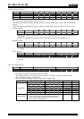
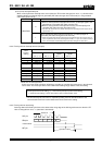
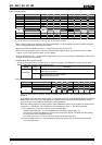
1) TSEL0,1 bits (Timer Select 0, 1)
The combination of these two bits is used to set the countdown period (source clock) for the fixed-cycle timer
interrupt function (four settings can be made).
TSEL0,1
TSEL1
(bit 1)
TSEL0
(bit 0)
Source clock
Auto reset time
tRTN
Effects of STOP
and RESET bits
0 0 4096 Hz
/Once per 244.14 µs
122 µs −
0 1 64 Hz /
Once per
15.625
ms
7.8125 ms
1 0 "Second" update /Once per second
7.8125 ms
Write/Read
1 1 "Minute" update /Once per minute
7.8125 ms
∗
Does not operate
when the STOP bit
or RESET bit value
is "1".
∗1) The /INT pin's auto reset time (tRTN) varies as shown above according to the source clock setting.
∗2) When the source clock has been set to "second update" or "minute update", the timing of both
countdown and interrupts is coordinated with the clock update timing.
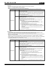
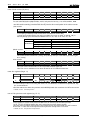
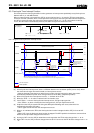
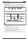
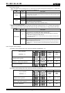
2) Fixed-cycle Timer Control register (Reg - B ∼ C)
This register is used to set the default (preset) value for the counter. Any count value from 1 (001 h) to
4095 (FFFh) can be set. The counter counts down based on the source clock's period, and when the count value
changes from 001h to 000h, the TF bit value becomes "1".
The countdown that starts when the TE bit value changes from "0" to "1" always begins from the preset value.
Be sure to write "0" to the TE bit before writing the preset value. If a value is written while TE = "1" the first
subsequent event will not be generated correctly.
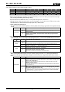
Address C
Timer Counter 1
Address B
Timer Counter 0
bit 7 bit 6 bit 5 bit 4 bit 3 bit 2 bit 1 bit 0 bit 7 bit 6 bit 5 bit 4 bit 3 bit 2 bit 1 bit 0
•
•
•
•
2048 1024 512 256 128 64 32 16 8 4 2 1
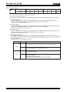
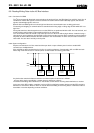
3) TE (Timer Enable) bit
This bit controls the start/stop setting for the fixed-cycle timer interrupt function.
TE
Data Description
0 Stops fixed-cycle timer interrupt function.
Write/Read
1
Starts fixed-cycle timer interrupt function.
∗
The countdown that starts when the TE bit value changes from "0" to "1" always begins from the
preset value.
4) TF (Timer Flag) bit
If set to "0" beforehand, this flag bit's value changes from "0" to 1" when a fixed-cycle timer interrupt event has
occurred. Once this flag bit's value is "1", its value is retained until a "0" is written to it.
TF
Data Description
0
The TF bit is cleared to zero to prepare for the next status detection
∗ Clearing this bit to zero does not enable the /INT low output status to be cleared (to Hi-Z).
Write
1 This bit is invalid after a "1" has been written to it.
0 Fixed-cycle timer interrupt events are not detected.
Read
1
Fixed-cycle timer interrupt events are detected.
(Result is retained until this bit is cleared to zero.)