


RX
-
8581
SA
/
JE
/
NB
Page - 26 MQ372-02
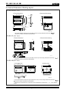
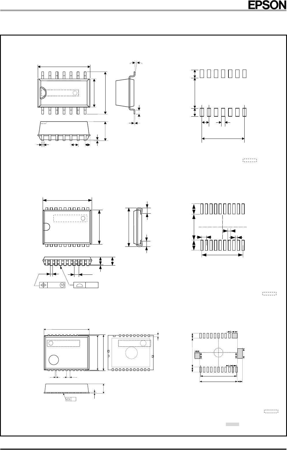
9. External Dimensions / Marking Layout
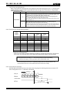
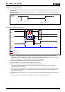
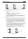
RX-8581 SA
(SOP - 14 pin)
• External dimensions • Recommended soldering
0.6
0.15
0° - 10°
1.4
1.4
5.4
1.27
1.27 × 6 = 7.62
0.7
Unit : mm
10.1
±
0.2
5.0
7.4
±
0.2
#14
#8
#7
#1
1.27 1.2
0.05
Min.
3.2
±
0.1
0.35
R8581
E 1234A
∗ The crystal oscillator's metal case may be visible in the area (on top) indicated in broken lines ,
but this has no effect on the device's characteristics.
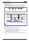
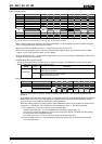
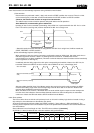
RX-8581 JE
(VSOJ - 20 pin)
• External dimensions • Recommended soldering
0.65
0.22
1.3
1.5 Max.
0.12 0.1
0 Min.
6.0
±
0.2
(0.75)
(0.75)
Unit : mm
1.5
3.8
1.5
0.65 × 9 = 5.85
0.3
0.35
0.65
5.4
7.0 ± 0.3
# 1
#20 #11
#10
R8581
E 1234A
∗ The crystal oscillator's metal case may be visible in the area (on front and top) indicated in broken lines ,
but this has no effect on the device's characteristics.
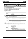
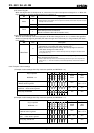
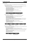
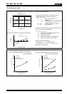
RX-8581 NB
(SON - 22 pin)
• External dimensions • Soldering pattern
1.3
±
0.1
0.125
0.1
Unit : mm
6.3 Max.
5.0
±
0.2
4.8
0.5 0.2
#1
#22
#14
#11
#14
(
0.3
)
#11
#1
#22
0.8
P 0.5 × 10 = 5.0
1.4
0.5
5.25
0.25
0.7
0.75 0.25
0.8
0.7
4.0 0.7 0.7
#1
#11
#22
#14
E 1234A
R8564
∗1)
The crystal oscillator's metal case may be visible in the area (on front and top) indicated in broken lines
,
but this has no effect on the device's characteristics.
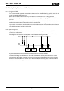
∗2)
Do not lay out signal patterns on component surfaces indicated by the shaded areas
in the soldering
diagram .