


RX
-
8581
SA
/
JE
/
NB
Page - 17 MQ372-02
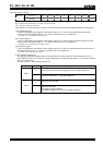
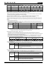
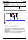
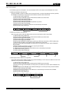
8.4.2. Related registers for time update interrupt functions.
Address Function bit 7 bit 6 bit 5 bit 4 bit 3 bit 2 bit 1 bit 0
D Extension Register
TEST WADA
USEL
TE
! !
TSEL1 TSEL0
E Flag Register
! !
UF
TF AF
!
VLF
!
F Control Register
! !
UIE
TIE AIE
!
STOP RESET
∗)
"o" indicates write-protected bits. A zero is always read from these bits.
∗ Before entering settings for operations, we recommend writing a "0" to the UIE bit to prevent hardware interrupts
from occurring inadvertently while entering settings.
∗ When the STOP bit or RESET bit value is "1" time update interrupt events do not occur.
∗ Although the time update interrupt function cannot be fully stopped, if "0" is written to the UIE bit, the time update
interrupt function can be prevented from changing the /INT pin status to low.
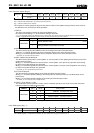
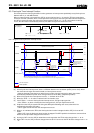
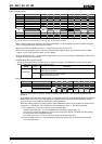
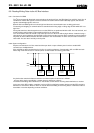
1) USEL (Update Interrupt Select) bit
This bit is used to select "second" update or "minute" update as the timing for generation of time update interrupt
events.
USEL
Data Description
0
Selects "second update" (once per second) as the timing for generation of
interrupt events
Write/Read
1
Selects "minute update" (once per minute) as the timing for generation of
interrupt events
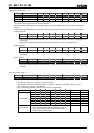
2) UF (Update Flag) bit
Once it has been set to "0", this flag bit value changes from "0" to "1" when a time update interrupt event occurs.
When this flag bit = "1" its value is retained until a "0" is written to it.
UF
Data Description
0
The UF bit is cleared to zero to prepare for the next status detection
∗
Clearing this bit to zero does not enable the /INT low output status to be cleared (to Hi-Z).
Write
1 This bit is invalid after a "1" has been written to it.
0 Time update interrupt events are not detected.
Read
1
Time update interrupt events are detected.
(The result is retained until this bit is cleared to zero.)
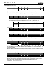
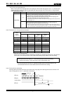
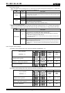
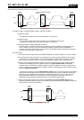
3) UIE (Update Interrupt Enable) bit
When a time update interrupt event occurs (UF bit value changes from "0" to "1"), this bit selects whether to
generate an interrupt signal (/INT status changes from Hi-Z to low) or to not generate it (/INT status remains
Hi-Z).
UIE
Data Description
0
1) Does not generate an interrupt signal when a time update interrupt event
occurs (/INT remains Hi-Z)
2) Cancels interrupt signal triggered by time update interrupt event (/INT
changes from low to Hi-Z).
∗
Even when the UIE bit value is "0" another interrupt event may change the /INT status to low (or
may hold /INT = "L").
Write/Read
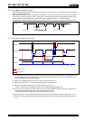
1
When a time update interrupt event occurs, an interrupt signal is generated
(/INT status changes from Hi-Z to low).
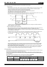
∗
When a time update interrupt event occurs, low-level output from the /INT pin occurs only when
the UIE bit value is "1". Up to 7.8 ms after the interrupt occurs, the /INT status is automatically
cleared (/INT status changes from low to Hi-Z).