


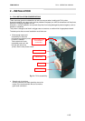

FENIX IMVICO
TK14 OPERATION MANUAL
15/65
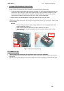
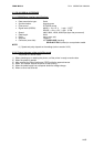
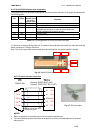
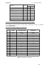
2.3.3- Serial RS-232 interface pins assignment
The assignments of the terminals of the RS-232 connector and the functions of its signals are described in
the following table:
Pin
Signal
name
Signal
direction (from
the printer
point of view)
Function
20 TXD Output Data transmission line.
21 RXD Input Data reception line.
22 RTS Output This signal indicates whether the printer is busy. SPACE
indicates that the printer is ready to receive data, and
MARK indicates that the printer is busy.
24 SG - Signal ground.
23 DTR Output This signal indicates whether an error occurs.
Other nc --- Not connected
Table 2.1-
Pins Assignments of RS-232 connector terminals.
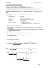
(*1) Definition of ‘data receiving buffer full’: the state of the printer becomes ‘buffer full’ when the receiving
buffer increases to 10 Kbytes maximum.
Note: The printer ignores the received data when the free space in the receiving buffer is 0 bytes.
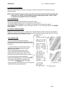
Fig. 2.6-
Serial RS-232 interface pins.
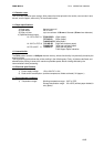
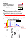
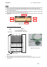
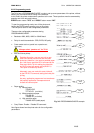
2.3.5- PC serial interface connection
Fig. 2.7-
PC serial cable.
NOTES:
•
Same configuration in the printer and in the host system should be set.
•
The communication protocol should be set properly so that the transmitted data can be received
without errors.
FEMALE DB9
Housing: PHDR-24VS (JST)
Contact: SPHD-001T-P0.5
(JST)
TK14
PC
shield to chassis
2
3
5
6
8
20
21
23/24
19
22
TXD
RXD
GND
DTR
RTS
RXD
TXD
GND
DSR
CTS
Pin #23
Pin #24
Pin #21Pin #19
Pin #20
Pin #22