


FENIX IMVICO
TK14 OPERATION MANUAL
18/65
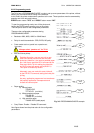
NOTES:
(1)
The ‘n’ prefix used before a signal name means that they are active in ‘0’ logic level. If the host system
does not provide any of the signal lines mentioned above, both communication types could fail.
(2)
It is recommended to use twisted pair cables (signal/ground), with the return sides connected to the
system signal ground level.
(3)
Do not ignore the nACK and BUSY signals during data transmissions. An attempt to transmit data
without nACK or BUSY control signals might cause lost data.
(4)
The interface cables should have the minimum required possible length (maximum recommended
length: 2 m).
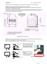
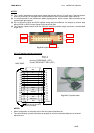
Fig. 2.8-
Parallel interface pins.
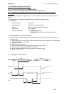
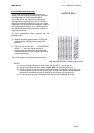
2.4.4- PC parallel interface connection
Fig. 2.9-
PC parallel cable.
NOTES:
•
Same configuration in the printer and in the host system should be set.
•
The communication protocol should be set properly so that the transmitted data can be received
without errors.
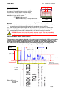
MALE DB25
Housing
:
PHDR-24VS (JST)
Contact:
SPHD-001T-P0.5 (JST)
TK14
PC
1
2
3
4
5
6
7
8
9
10
11
12
13
14
15
16
17
18/25
1
2
3
4
5
6
7
8
9
10
11
12
14
18
13
17
16
23/24
Shield to chassis
STB
D0
D1
D2
D3
D4
D5
D6
D7
BUSY
A
CK
PE
ERR
GND
SELECTIN
A
UTOFEED
SELECT
INIT
Pin #1
Pin #2
Pin #19
Pin #19
Pin #18
Pin #15 (nc)