Programmer’s Guide, cont’d
CrossPoint Plus Matrix Switchers • Programmer’s Guide4-2
Programmer’s Guide
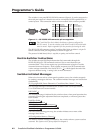
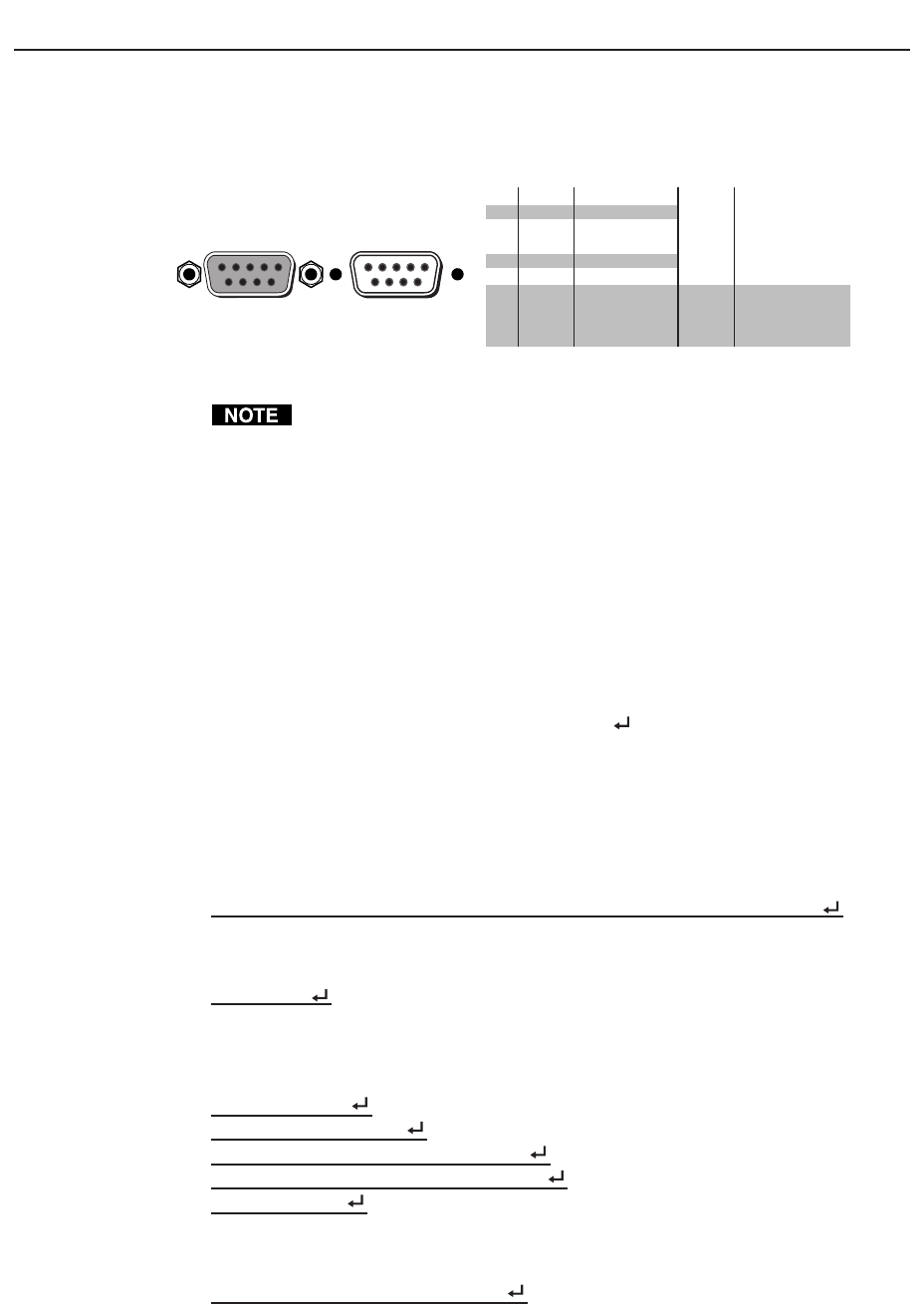
The switcher’s rear panel RS-232/RS-422 connector (figure 4-1) can be connected to
the serial port output of a host device such as a computer, RS-232 capable PDA, or
control system. This connection makes software control of the switcher possible.
Female
51
96
Male
15
69
RS-232 FunctionPin
1
2
3
4
5
6
7
8
9
—
TX
RX
—
Gnd
—
—
—
—
Not used
Transmit data
Receive data
Not used
Signal ground
Not used
Not used
Not used
Not used
RS-422 Function
TX-
TX+
RX+
RX-
Gnd
—
—
—
—
Transmit data (-)
Transmit data (+)
Receive data (+)
Receive data (-)
Signal ground
Not used
Not used
Not used
Not used
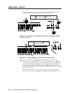
Figure 4-1 — RS-232/RS-422 connector pin arrangement
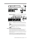
The CrossPoint Plus Series Matrix Switchers are factory configured for
RS-232 control. To use the switcher under RS-422 control, an internal cable
must be moved. Refer to appendix B for the procedure for moving the cable.
The RS-232/RS-422 connector on the CrossPoint Plus Series switcher is a 9-pin D
female connector with pin assignments as shown in figure 4-1.
The protocol is 9600 baud, 8-bit, 1 stop bit, no parity, and no flow control.
Host-to-Switcher Instructions
The switcher accepts SIS (Simple Instruction Set) commands through the
RS-232/RS-422 port. SIS commands consist of one or more characters per
command field. They do not require any special characters to begin or end the
command character sequence. Each switcher response to an SIS command ends
with a carriage return and a line feed (CR/LF = ), which signals the end of the
response character string. A string is one or more characters.
Switcher-Initiated Messages
When a local event such as a front panel operation occurs, the switcher responds
by sending a message to the host. The switcher-initiated messages are listed below
(underlined).
(C) Copyright 2002, Extron Electronics “CrossPoint/Mav/Matrix”, Vx.xx
The copyright message is initiated by the switcher when it is first powered on.
Vx.xx is the firmware version number.
RECONFIG
The reconfig message is initiated by the switcher when a front panel operation has
occurred, an audio gain adjustment has been completed, or a memory preset has
been recalled.
RAM Test Failed
ROM Checksum Failed
EEPROM Reset (Presets/Attenuators)
Serial EEPROM Reset (Current Settings)
Invalid Jumpers
If an error occurs during power-up, the switcher initiates one or more of the
messages listed above.
All Configuration Memory Cleared
The memory cleared message is initiated by the switcher when a system reset has
occurred. See System reset to factory defaults in chapter 3.


