


FOX Matrix 3200 and FOX Matrix 7200 • Maintenance and Modifications 2726 FOX Matrix 3200 and FOX Matrix 7200 • Remote Control
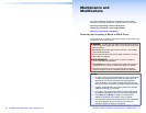
Maintenance and
Modifications
This section describes repairing and reconguring the FOX matrix
switchers by replacing components. Topics that are covered include:
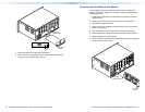
Removing and Installing a Board or Blank Panel
Removing and Installing a Power Supply Module
Removing and Installing a Fan Module
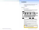
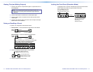
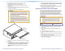
Removing and Installing a Board or Blank Panel
Circuit boards can be added or removed to increase or decrease the I/O
conguration (size) of the switcher.
WARNING: The ber optic I/O boards of the FOX matrix switchers
output continuous invisible light, which may be harmful to the eyes;
use with caution.
Do not look into the ber optic cable connectors or into the ber
optic cables themselves.
Plug the attached dust caps into the optical transceivers when the
ber cable is unplugged.
AVERTISSEMENT: L'appareil émet une lumière invisible en
continu, à utiliser avec precaution.
Ne regardez pas dans les connecteurs de câble bre optique sur
le panneau arrière ou dans les câbles bre optique eux-mêmes.
Branchez les protections contre la poussière dans l'ensemble
émetteur/récepteur lorsque le câble bre optique est débranché.
NOTES:
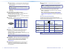
• On a ber optic I/O board as delivered from Extron, all transceiver
modules are congured the same: either all multimode or all
singlemode. You can mix multimode and singlemode ber
optic I/O boards in a FOX matrix switcher, but ensure that you
connect the proper transmission mode ber cables to the board.
• Typically, singlemode ber has a yellow jacket and multimode
cable has an orange or cyan jacket.
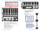
• For proper cooling and air ow, boards or blank panels should
be installed in all locations during normal switcher operations.
• See A Note on I/O Boards on page 5 to understand the
different arrangement of connectors on the I/O boards.
• The FOX Matrix Switcher components that are user-replaceable
are hot-swappable. You do not need to power down the
switcher to remove or replace a component.