


FOX Matrix 3200 and FOX Matrix 7200 • Installation 54 FOX Matrix 3200 and FOX Matrix 7200 • Introduction
Installation
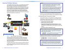
This section describes installation of the FOX matrix switchers, including
connections and features. Topics that are covered include:
• Rear Panel
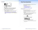
• Front Panel
Rear Panel
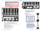
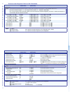
A Note on I/O Boards
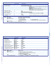
As shown in gure 2, each I/O board is identied by the input and output
numbers supported by the board position. The transceiver modules on
the I/O boards are identied as A through H.
ANAHEIM, CA
100-240V 50/60Hz 1.2A MAX.
PRIMARY POWER SUPPLY
1 - 8
9 - 16
17 - 24
A
B
C
D
E
F
OUT
IN
OUT
IN
OUT
IN
OUT
IN
OUT
IN
OUT
A
B
C
D
E
F
OUT
IN
OUT
IN
OUT
IN
OUT
IN
OUT
IN
OUT
IN
25 - 32
MUTI-RATE SDI INPUTS
H
G
AD
E
F
C
B
D
C
AD
C
B
Location A
Input
Location A
Output and Input
Slot 1
(1-8)
O#1
I#1
Slot 2
(9-16)
Slot 3
No board
installed
Slot 4
(25-32)
O#2
I#2
O#3
I#3
O#4
I#4
O#9
I#25
I#26
I#27
I#28
I#29
I#30
I#31
I#32
O#25
O#26
I#9
O#10
I#10
O#11
I#11
O#12
I#12
O#5
I#5
O#6
O#13
I#13
O#14
Location A
Output
Location H
Input
AA
AA
BB
Figure 2. Arrangement of Inputs and Outputs on the I/O Boards
The board position designators, printed beside the fans, correspond to
the input and output numbers served by that position (1 - 8, 9 - 16, and
so on).
The location designators, A through H, correspond to the transceiver
modules, numbered from left to right, each of which includes an input
and an output.
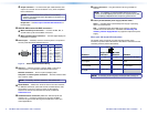
See gure 2. The input and output numbers supported by the I/O board
in slot 2 (location 9 - 16) are as follows: A = 9, B = 10, C = 11, D = 12,
E = 13, F = 14, G = 15, and H = 16.
ATTENTION:
• Turn off power to the input and output devices, and disconnect
their power cords before making connections.
• Débranchez le produit et les autres appareils.