


8 FOX Matrix 3200 and FOX Matrix 7200 • Installation 9FOX Matrix 3200 and FOX Matrix 7200 • Installation
Õ
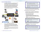
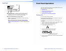
Output connector — Connect a fiber optic cable between each
output LC connector and a FOX 500 Rx or any other compatible
Extron FOX device.
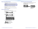
NOTE: Or, for the serial return (receiver-to-transmitter)
function, connect the far end to the Optical 2 connector on a
FOX Tx transmitter.
Output LED — See Fiber optic I/O board LED indications on
the next page.
B
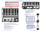
SDI/HDI-SDI boards with BNC connectors —
Ï
Multi-rate SDI Input connectors — Connect HD-SDI, SDI, or
3G-SDI video inputs to these BNC connectors.
Ö
Multi-rate SDI Output connectors — Connect digital displays to
these BNC connectors.
C
Remote port — If desired, connect a control system or computer to
the rear panel Remote RS-232/RS-422 port.
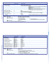
RS-232 Function Pin Function
1
2
3
4
5
6
7
8
9
—
Tx
Rx
—
Gnd
—
—
—
—
Not used
Transmit
Receive
Not used
Ground
Not used
Not used
Not used
Not used
—
Tx–
Rx–
—
Gnd
—
Rx+
Tx+
—
Not used
Transmit (–)
Receive (–)
Not used
Ground
Not used
Receive (+)
Transmit (+)
Not used
RS-422
5
1
96
Figure 5. Audio Output Connector Wiring
D
LAN port — If desired, connect a network WAN or LAN hub, a
control system, or a computer to the Ethernet RJ-45 port.
Network connection — Wire as a patch (straight) cable.
Computer or control system connection — Wire the interface cable
as a crossover cable.
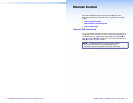
NOTE: The factory default IP address is 192.168.254.254.
E
Reset button — Initiates four levels of reset of the matrix switcher.
For different reset levels, press and hold the recessed button while
the switcher is running or while you power up the switcher.
See the FOX 3200 and 7200 Series User Guide, available at
www.extron.com.
F
Switch Reference connectors (affect SDI / HD-SDI inputs and
outputs only) — Connect an external sync signal to this BNC
connector to genlock the video signal in broadcast or other sync-
critical applications.
G
Power connectors — Plug the switcher into two grounded AC
sources.
NOTE: For reliability, connect the Redundant power cord to
either an uninterruptible power source or to a power source that
is completely independent from the primary power source.
H
Primary and Redundant power supply indicator LEDs —
Green — Indicates that the associated power supply is operating
within normal tolerances.
Red — Indicates that the associated power supply is operating
outside the normal tolerances or has failed. See Removing and
Installing a Power Supply Module on page 29 to replace the power
supply.
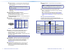
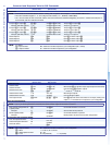
Fiber optic I/O board LED indications
On the ber optic I/O boards, the input and output LEDs on the
transceivers provide useful indications of the status of the lasers and the
reclocking function (see the table below).
OUT
IN
Definition
Output LED
indication
Input LED
indication
Definition
Reclocked at 4.25 Gbps
On On
Reclocked at 4.25 Gbps
Not reclocked, laser off,
or no signal
Off Off
Not reclocked or no
signal
Non-4G signal present or
not reclocked
Fast blink Fast blink
Non-4G signal present or
not reclocked
Not reclocked, laser on or
no signal
Slow blink Slow blink N/A
NOTE: If reclocking is set to bypass, the Output LED is always on.