


28 FOX Matrix 3200 and FOX Matrix 7200 • Maintenance and Modifications 29FOX Matrix 3200 and FOX Matrix 7200 • Maintenance and Modifications
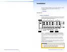
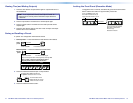
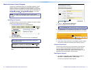
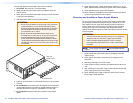
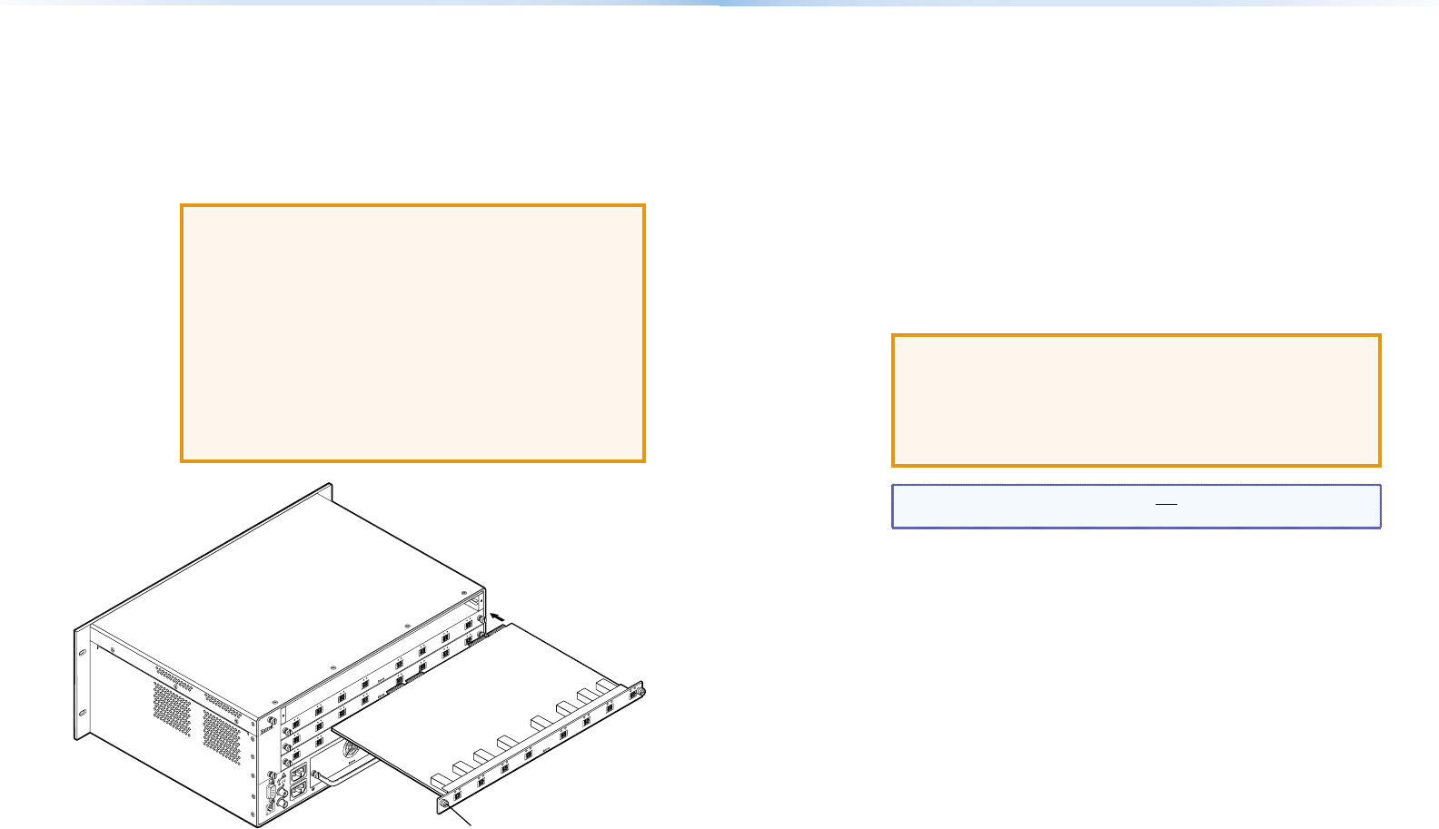
Remove and replace and I/O board or blank panel as follows:
1. For a board, disconnect any connected cables.
2. Rotate the left and right knurled knobs to completely loosen the
captive screws.
3. Gently pull on the knurled knobs/captive screws to loosen the board
or panel from the backplane.
4. Slide the board or panel out of the chassis (below).
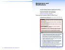
ATTENTION:
• Do not touch the electronic components or the connectors
on the backplane or on the circuit boards without being
electrically grounded. Handle circuit boards by their edges
only. Electrostatic discharge can damage circuits, even if
you cannot feel, see, or hear it.
• Ne pas toucher les composants électroniques ou les
connecteurs sur la carte mère ou sur les circuits imprimés
sans être électriquement relié à la terre. Manipuler les
circuits imprimés en les tenant seulement par leurs bords.
Les décharges électrostatiques (ESD) peuvent endommager
l'équipement, même si vous ne pouvez pas le sentir, le voir
ou l'entendre.
ANAHEIM, CA
RESET
REMOTE
RS-232/RS-422
LAN
BI-LEVEL
TRI-LEVEL
ACT LINK
100-240V 50/60Hz 1.2A MAX.
100-240V 50/60Hz 1.2A MAX.
REDUNDANT
PRIMARY
DISCONNECT BOTH POWER
CORDS BEFORE SERVICING
SWITCH
REFERENCE
PRIMARY POWER SUPPLY
REDUNDANT POWER SUPPLY
1 - 8
9 - 16
A
B
C
D
E
F
G
H
OUT
IN
OUT
IN
OUT
IN
OUT
IN
OUT
IN
OUT
IN
OUT
IN
OUT
IN
OUT
17 - 24
A
B
C
D
E
F
G
H
OUT
IN
OUT
IN
OUT
IN
OUT
IN
OUT
IN
OUT
IN
OUT
IN
OUT
IN
OUT
25 - 32
A
B
C
D
E
F
G
H
OUT
IN
OUT
IN
OUT
IN
OUT
IN
OUT
IN
OUT
IN
OUT
IN
OUT
IN
OUT
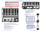
Align with
Plastic Guides
IN
OUT
IN
A
OUT
IN
B
OUT
IN
C
OUT
IN
D
OUT
IN
E
OUT
IN
F
OUT
IN
G
OUT
IN
H
Knurled Knobs
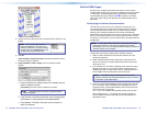
5. Place the removed board on an anti-static surface or in an anti-static
container.
6. For an I/O board, orient the board to be installed so that transceiver
module A (ber board) or input BNC A (3G/HD-SDI/SDI board) is on
the left and transceiver module or output BNC H is on the right.
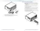
7. For an I/O board, align the board with the left and right chassis
guides.
8. Gently slide the board or blank panel into the enclosure. For an I/O
board, slide the board toward the front panel until it meets resistance.
9. Gently seat the board or panel in the backplane.
10. Use a screwdriver to tighten the left and right knurled knob captive
screws to lock the board or panel in place.
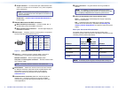
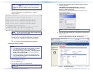
Removing and Installing a Power Supply Module
The two power supply modules (primary power supply and redundant
power supply) are identical. Each power supply module has a 2-color
LED, visible on the rear panel, that indicates the status of the power
supply outputs. If the LED is lit green, the power supply is operating
normally. If the LED is lit red, the supply has failed and should be
replaced at the earliest opportunity. LEDs with identical meaning are also
on the front panel.
ATTENTION:
• This unit uses double pole/neutral fusing. Do not operate the
equipment with only one power supply cord connected.
• Cette unité utilise double pôles/fusion neutre. N'utilisez
pas l'équipement avec seulement un cordon d'alimentation
connecté.
NOTE: Power supply modules are not interchangeable between
models.
1. Rotate the left and right knurled knobs to completely loosen the
captive screws.
2. Gently pull on the handle to loosen the power supply from the
backplane.
3. Slide the power supply out of the chassis.
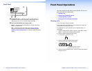
4. Orient the power supply module to be installed with the LED to the
right.
5. Align the anges on the power supply module with the left and right
power supply guides (see the next page).
6. Gently slide the power supply module into the enclosure until the
power supply meets resistance.