


Video and Audio Input Connections
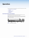
a RGB video inputs — Connect the analog computer-video sources to
1
these 15-pin HD female connectors.
NOTE: Most laptop or notebook computers have an external video port, but they
require special commands to output the video to that connector. Also,
a laptop screen shuts off once that port is activated. See the user guide
for the computer for details, or contact the Extron S3 Sales and Technical
Support Hotline for a list of common laptop keyboard commands (see
the contact numbers on the last page of this guide for the Extron office
nearest you).
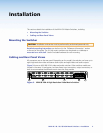
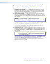
Audio inputs — Connect the
unbalanced stereo audio sources to these
1
3.5 mm mini stereo jacks for unbalanced audio input. Figure 3 shows how to
wire the audio plug.
Tip (L) Sleeve (Gnd)
Tip (L)
Ring (R)
Sleeve (Gnd)
Figure 3. Audio Input Connector Wiring
Video and Audio Output Connections
b RGB video output connectors — Connect RGBHV video displays to these
15-pin HD female connectors for each output.
NOTES: • The MVX switchers can also switch RGBS, RGsB, RsGsBs, or
component/HDTV video.
• The MVX switchers do not alter the video signal in any way. The signal
output by the switcher is in the same format as the input.
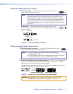
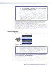
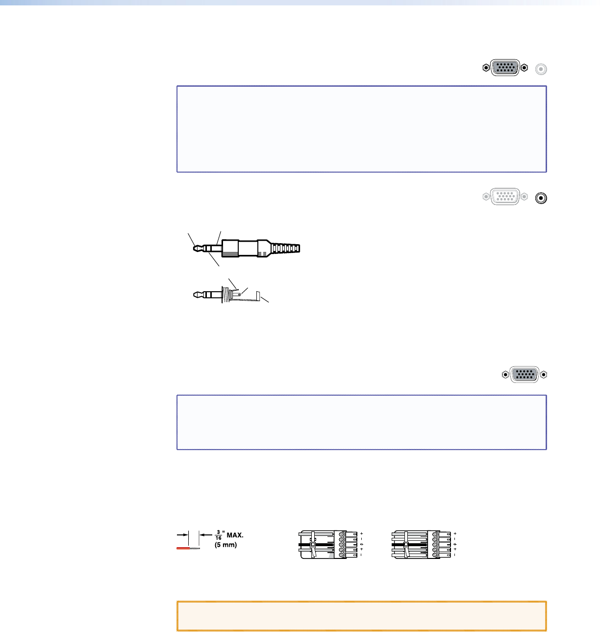
c Balanced or unbalanced audio output connectors — These 3.5 mm, 5-pole captive
screw connectors output the selected unamplified, line level audio. Connect audio
devices, such as an audio amplifier or powered speakers.
See figure 4 to properly wire an output connector. Use the supplied tie-wrap to strap
the audio cable to the extended tail of the connector.
Ring
Sleeve(s)
Tip
Tip
Ring
Sleeve(s)
Tip
Tip
Unbalanced Stereo Output Balanced Stereo Output
NO GROUND HERE.
NO GROUND HERE.
LR
Do not tin the wires!
Figure 4. Captive Screw Connector Wiring for Audio Output
CAUTION: For unbalanced audio, connect the sleeves to the ground contact.
DO NOT connect the sleeves to the negative (-) contacts.
MVX 44 / 48 / 84 / 88 VGA Matrix Switchers • Installation 5