


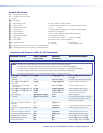
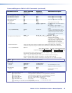
Command/Response Table for SIS Commands (continued)
Command Function
ASCII Command
(Host to Unit)
Response
(Unit to Host)
Additional description
View ties, gains, mutes, and presets
Read RGB
(video) output tie
X@
&
X!]
RGB input
X!
is tied to output
X@
.
Read RGB (video) output tie
X@
%
X!]
RGB input
X!
is tied to output
X@
.
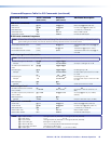
Read audio output tie
X@
$
X!]
Audio input
X!
is tied to output
X@
.
View input gain
X$
G
X^]
Example:
3G
-06
]
Audio input 3 level is -6 dB.
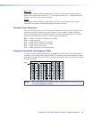
View output mutes
E
VM
} X1)
1
X1)
2
...
X1)
n
Mut
]
Each
X1)
response is the mute status of
an output:
left = output 1, right = output n.
n = the highest output number for this
model.
Example (MVX 84 VGA):
E
VM
}
0132Mut
]
Output 1 is unmuted, output 2 video
is muted, output 3 video and audio are
muted, and output 4 audio is muted.
Outputs 5 through 8 are not present
on this switcher.
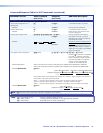
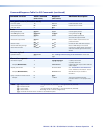
View global preset conguration
EX(
1VC
} X!
1
•
X!
2
•
X!
3
•...•
X!
n
•Vid•
X!
1
•
X!
2
•
X!
3
•...•
X!
n
•Aud
]
Show the video and audio
configuration for preset
X(
. Show the
video input tied to n sequential outputs
and then the audio input tied to n
sequential outputs. n is the highest
output number for this model switcher.
Response description: Video input # (I#) tied to output #1 (O#1)•I# tied to O#2•I# tied to O#3•I# tied to O#n•Vid•
Audio input # (I#) tied to output #1 (O#1)•I# tied to O#2•I# tied to O#3•I# tied to O#n•Aud
]
Example (MVX 88 VGA):
E
4VC
}
6•5•6•8•3•3•1•0•Vid•8•1•1•1•8•8•8•8•Aud
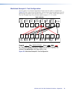
1Output:
Response = tied input:
Input 5 video tied to output 2
23456781234 5 6 7 8
No tied input A
udio input 8 tied to output 5
Each position shown in the response is an output: left = output 1 , right = output 8. The number in
each position is the input tied to that output.
Video — Input 6 is tied to outputs 1 and 3; input 5 to output 2; input 8 to output 4;
input 3 to outputs 5 and 6; and input 1 to output 7. No input is tied to output 8.
Audio — Input 8 is tied to outputs 1 and outputs 5 through 8; input 1 to outputs 2 through 4.
NOTE:
E
0VC
}
returns the current video and audio configuration of the switcher.
RGB delay
Set RGB delay
EX@
*
X1!
D
}
Out
X@
•Dly
X1!]
Example:
E
5*7D
}
Out5•Dly07
]
Set the RGB delay for a tie to
output 5 to 3.5 sec (7 x 0.5 sec.).
Read RGB delay
EX@
D
} X1!]
Example:
E
6D
}
05
]
Output 6 delay is 2.5 sec
(5 x 0.5 sec.).
NOTE: X! = Input number (for tie) 0 (untie) – maximum number of inputs
X@ = Output number 1 through 4 (MVX 44, MVX 84) or 1 through 8 (MVX 48, MVX 88)
X$ = Input number 1 through 4 (MVX 44, MVX 48) or 1 through 8 (MVX 84, MVX 88)
X^ = Numeric dB value –18 to +10 (29 steps [dB] of audio attenuation and gain
X( = Preset number 00 through 16 (00 = current configuration)
X1) = Video/audio mute 0 = no mutes 2 = audio mute
1 = video mute 3 = video and audio mute
X1! = RGB delay in ½ second increments (10 [5 seconds] maximum)
MVX 44 / 48 / 84 / 88 VGA Matrix Switchers • Remote Operation 42