


MVX VGA A Matrix Switchers • Installation
Installation
MVX VGA A Matrix Switchers • Installation
2-2
Refer also to the MVX VGA A User’s Manual at www.extron.com.
2-3
Refer also to the MVX VGA A User’s Manual at www.extron.com.
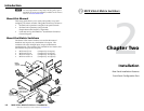
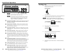
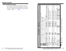
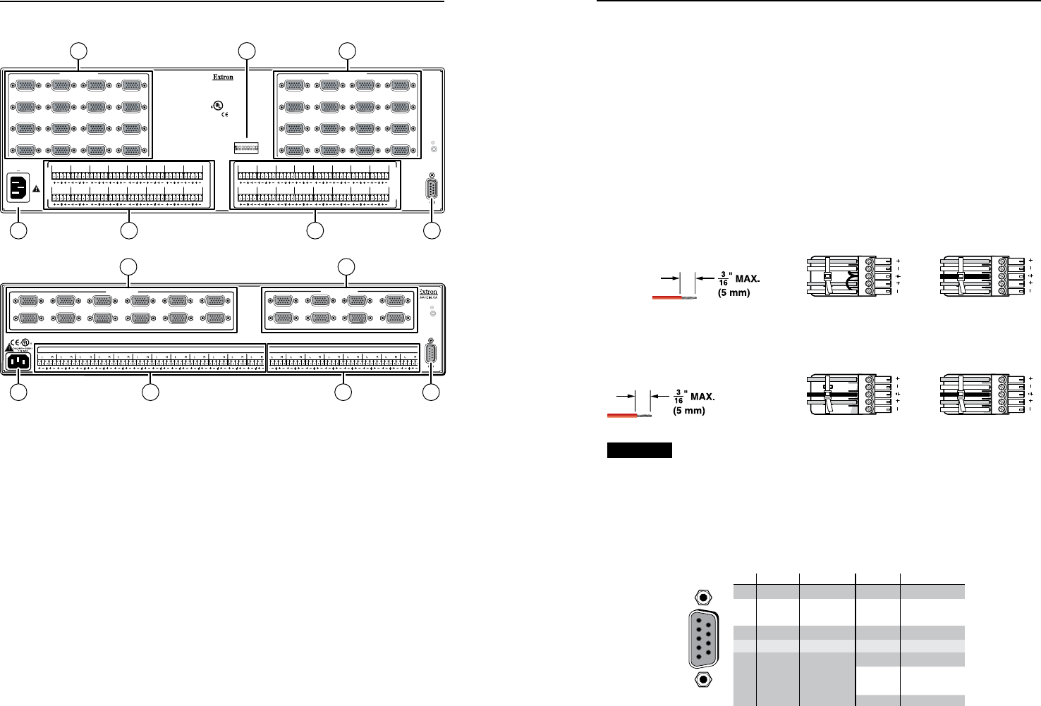
Rear Panel Installation Features
RS-232/RS422
REMOTE
RESET
COMPUTER IN
1
2
5
6
9
10
13
14
3
4
7
8
11
12
15
16
COMPUTER OUT
1
2
5
6
9
10
13
14
3
4
7
8
11
12
15
16
1.2A MAX.
100-240V 50/60 Hz
O
U
T
P
U
T
S
I
N
P
U
T
S
L
15
RL
13
RL
11
RL
9
RL
7
RL
5
RL
3
RL
1
R
L
16
RL
14
RL
12
RL
10
RL
8
RL
6
RL
4
RL
2
R
L
15
RL
13
RL
11
RL
9
RL
7
RL
5
RL
3
RL
1
R
L
16
RL
14
RL
12
RL
10
RL
8
RL
6
RL
4
RL
2
R
1 2 34 5 67 8
12 3 45
50
75
OUTPUT
SYNC IMPEDANCE
678
Anaheim, CA
US
LIS TED
1T23
I.T.E.
®
COMPUTER IN COMPUTER OUT
OUTPUT
MVX 1616 VGA A
7 6
3
1 2
54
COMPUTER IN COMPUTER OUT
RS232/RS422
REMOTE
LISTED
1T23
I.T.E.
1 2 3 4 5 6 7 8
9 10 11 12
1 2 3 4 5 6 7 8
1
2
3
4
5
6
7
8
9
10
11
12
1
2
3
4
5
6
7
8
INPUTS
OUTPUTS
RESET
COMPUTER IN
COMPUTER OUT
MVX 128 VGA A
7 6
1 2
54
C
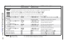
Turn off power to the input and output devices, and
disconnect their power cords.
N
The MVX matrix switchers can also switch component
video, S-video, or composite video with the appropriate
adapters.
a
Video inputs — Connect RGB video sources, as appropriate to
your switcher's video format and matrix size.
b
Video outputs — Connect RGB video displays, as appropriate
to your switcher's video format and matrix size.
N
Most laptop or notebook computers have an external
video port that may require special commands to output
the video to that connector. Also, a laptop’s screen shuts
off once the external video port is activated. See the
computer’s user’s guide for details, or contact Extron for a
list of common laptop keyboard commands.
N
The MVX VGA 128 A does not have the Sync Impedance
switches described below.
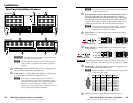
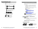
c
Sync Impedence switches (168, 1212, and 1616 matrix sizes) —
The Sync Impedance switches compensate the output 1
through 8 impendance for different cable types and lengths.
Each switch provides the option of selecting either 50 ohms or
75 ohms. The 50 ohms position is required only when a sync
problem is encountered. The normal position is 75 ohms.
N
An input producing an out-of-sync display — a display
that is rolling vertically and/or tearing horizontally —
could indicate an impedance problem.
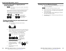
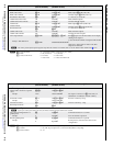
d
Audio inputs — Connect audio sources to the 5-pole captive
screw connectors.
Unbalanced Stereo Input
Balanced Stereo Input
Ring
Sleeve (s)
Tip
Sleeve
Tip
Sleeve
Tip
Tip
Ring
Do not tin the wires!
L R
e
Audio outputs — Connect audio devices to the 5-pole captive
screw connectors.
CAUTION
For unbalanced stereo audio, connect the sleeve(s) to the ground
contact. DO NOT connect the sleeve(s) to the negative (-) contacts.
Unbalanced Stereo Output
Balanced Stereo Output
L R
Ring
Tip
Sleeve(s)
Tip
Ring
Sleeve(s)
Tip
Tip
NO GROUND HERE.
NO GROUND HERE.
Do not tin the wires!
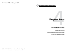
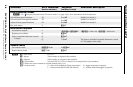
f
Remote port — If desired, connect a control or computer to the
rear panel Remote RS-232/RS-422 port.
N
Remote port defaults: RS-232, 9600 baud, no parity, 8-bit,
1 stop bit, no flow control.
RS-232 Function Pin Function
1
2
3
4
5
6
7
8
9
—
TX
RX
—
Gnd
—
—
—
—
Not used
Transmit
Receive
Not used
Ground
Not used
Not used
Not used
Not used
—
TX–
RX–
—
Gnd
—
RX+
TX+
—
Not used
Transmit (–)
Receive (–)
Not used
Ground
Not used
Receive (+)
Transmit (+)
Not used
RS-422
5
1
9
6
g
Power — Plug the switcher into a grounded AC source.