RGB 138xi, RGB 158xi Installation and Operation
RGB 138xi, RGB 158xi Installation and Operation
Installation and Operation, cont’d
The jumpers perform the following functions:
J-20: Sync polarity jumper — This jumper adjusts
the output sync polarity. Horizontal (H) and
vertical (V) sync output can either follow
input sync polarity, or be forced to negative.
• If the jumper is placed on pins 1 and 2, output
H and V sync polarities will be forced to
negative.
• If the jumper is placed on pins 2 and 3, output
sync polarities follow input sync polarity:
the output sync signals’ polarity will be
the same as the input polarity.
This is the default setting.
J-40: Vertical sync width jumper — This jumper
adjusts the vertical sync pulse width. Some
digital display devices have very specific
requirements for incoming sync pulse width.
If no picture displays, the picture cuts in and
out, or the picture is scrambled, try adjusting
the vertical sync pulse width or switching
from ADSP to DDSP.
• If the jumper is placed on pins 1 and 2, the
output vertical sync pulse will be
short (narrow).
• If the jumper is placed on pins 2 and 3, the
output vertical sync pulse will be wide.
This is the default setting.
5. Replace and fasten the enclosure cover, reversing step 2.
If adapter plates will be installed next, this step can
be omitted.
Negative
ollow
1
Wide
hort
1
Installing Adapter Plates
The RGB 138xi and RGB 158xi offer the ability to incorporate
a variety of optional architectural adapter plates for pass-
through audio and/or video connections. Each interface
can hold up to four (4) adapter plates.
Blank plates (two single height and one double height
plate) are included with the interface to cover unused
spaces. Other adapter plates must be ordered separately.
The plates attach to the front panel. Output cables attached
to the rear of each plate pass through the interface
enclosure and rear panel and are held in place by clamps.
Some adapters require wires to be soldered to the rear
connectors.
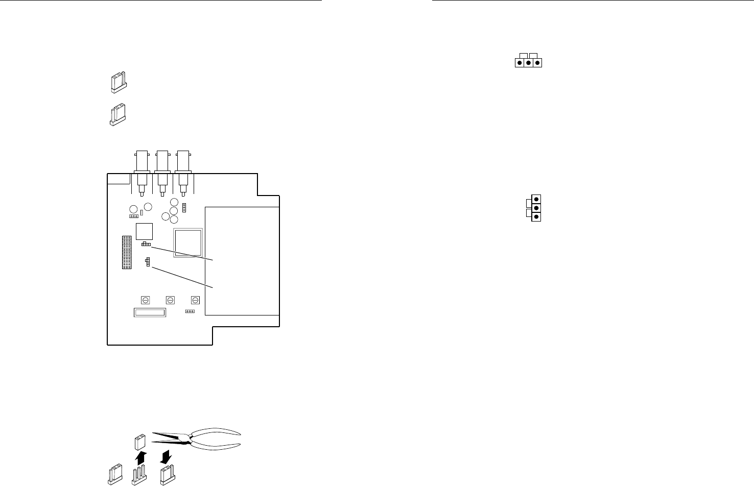
3. Note the positions of jumpers J20 and J40 before
changing jumper settings. The illustration of the
circuit board (below) shows the locations of the J20
and J40 jumpers. There are two possible setting
combinations for 3-pin jumpers:
pins 1 and 2 connected, and
pins 2 and 3 connected.
Circuit board jumper locations
4. Configure the jumpers. To configure the jumpers, use
pliers to pull the jumper shunt off the pins, then
place the jumper on the appropriate pins.
Changing jumper settings
1 and 2
2 and 3
J19
1
J40
1
J20
1
Front
Rear
Power Supply
J20: Sync
polarity
jumper
J40: Vertical
sync
width
jumper
2-10 2-11


