


RGB 138xi, RGB 158xi Installation and Operation
RGB 138xi, RGB 158xi Installation and Operation
Installation and Operation, cont’d
If the edges of the image seem to exceed their
boundaries or if thin lines and sharp edges look
thick and fuzzy, try changing the gain/peak setting.
4
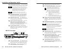
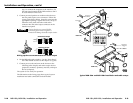
DIP switches — Three of the four DIP switches on
the rear panels are common to both the RGB 138xi
and the RGB 158xi. They control sync on green
(SOG) output, Digital Display Sync Processing and
serration pulse removal.
The fourth switch controls video input termination
(75 ohm vs. Hi Z) in the RGB 138xi, and it has no
function (spare) in the RGB 158xi.
1 — SOG (sync on green)
ON — When this switch is set to On, the
interface will output sync on green.
OFF — When the SOG switch is set to Off, the
interface outputs both separate
horizontal and vertical sync (on the H
and V connectors) and composite sync
(on the S connector) for RGBHV or
RGBS, respectively.
2 — DDSP™ (Digital Display Sync Processing™)
This feature may be necessary for digital display
devices such as LCD (liquid crystal display),
DLP (digital light processing) and plasma
displays. Use this option if the image still is not
displayed properly after all other options, such
as serration pulse removal and video
termination changes, have been explored.
ON — When this switch is set to On, the
interface uses Digital Display Sync
Processing instead of Advanced Digital
Sync Processing™. DDSP does not
process the sync signal.
DDSP will disable horizontal and vertical
shift controls.
OFF — When this switch is set to Off, the
interface performs sync processing
operations, such as horizontal shifting,
with ADSP.
3 — SERR (serration pulse) — Many display
devices, including LCD and DLP projectors and
plasma displays, must have serration pulses
removed from the sync signal in order to display
2-7
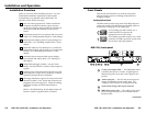
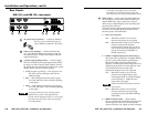
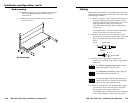
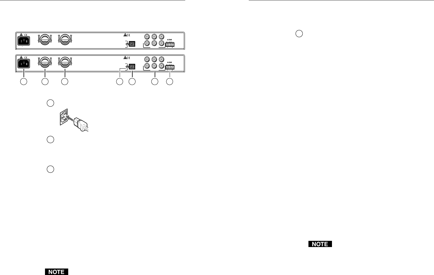
Rear Panels
RGB 138xi and RGB 158xi rear panels
1
AC power input connector — Connect a standard
IEC AC power cord here for power
input (100VAC to 240VAC, 50/60 Hz).
2
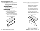
Cable access openings — Cables attached to the
A/V pass-through architectural adapter plates exit
the enclosure here. Clamp cables in place with the
supplied hardware.
3
3-position gain/peaking switch — Use this toggle
switch to compensate for signal degradation caused
by long (over about 125 feet) cable lengths. Choose
the setting that provides the best image on the output
display device. Select from these options:
• Unity (no gain or peaking) — The output level is
the same as that of the input and with no
added peaking.
• 50% — This setting increases the output signal
level and adds 50% of the maximum peaking
to the signal.
• 100% — This setting increases the output signal
level and adds 100% of the maximum peaking
to the signal.
If the signal cable between the interface and the
display device is shorter than approximately
125 feet, and the gain/peak switch is set to a setting
other than unity, the image may be overly bright
(overcompensated).
SOG
DDSP
SERR
75 Ohm
100-240 50/60 Hz 0.5A
OUTPUT
R
H
G
V
B
S
SOG
DDSP
SERR
SPARE
100-240 50/60 Hz 0.5A
OUTPUT
R
H
G
V
B
S
UNITY
50%
100%
GAIN/
PEAK
UNITY
50%
100%
GAIN/
PEAK
1 2 4
6
2 5
3
2-6