RGB 138xi, RGB 158xi Installation and Operation
RGB 138xi, RGB 158xi Installation and Operation
Installation and Operation, cont’d
2-17
Cabling
Attach cables to the interface as detailed in the steps below.
A diagram later in this section shows how the system looks
when cabling is finished.
1. Connect the computer’s video output to the interface’s
front panel analog/ECL 9-pin D connector. If the
computer will provide the audio input, a VGA with
audio combination cable, such as an Extron
VGA HRA series cable (#29-491-01 to #29-491-05),
can be used.
For the RGB 138xi, a monitor breakout cable (MBC)
can be used to allow local monitor output.
2. Connect the stereo audio source (computer or other
device such as a CD player or tape deck) to the front
panel. The audio jack should be wired as shown
below.
Tip (+) Sleeve (GND)
Tip (L, +)
Ring (R, -)
Sleeve (GND)
3. Connect the video output device’s (projector’s,
monitor’s) coaxial BNC cable to the rear panel BNC
connectors.
For RGBHV (separate H and V sync) output,
connect the cables as shown at left.
For composite sync (RGBS), connect the sync
cable to the connector labeled “S”.
For sync on green (SOG, RGsB), connect the
cables as shown here, and also select the SOG
option on the rear panel DIP switch.
4. Connect the local monitor. For the RGB 158xi, connect
the monitor’s cable to the front panel 15-pin HD
female local monitor output connector.
For the RGB 138xi, a local monitor can be connected
to the monitor breakout cable if one were used in
RGBHV
R
H
G
V
B
S
RGBS
R
H
G
V
B
S
RGsB
R
H
G
V
B
S
2-16
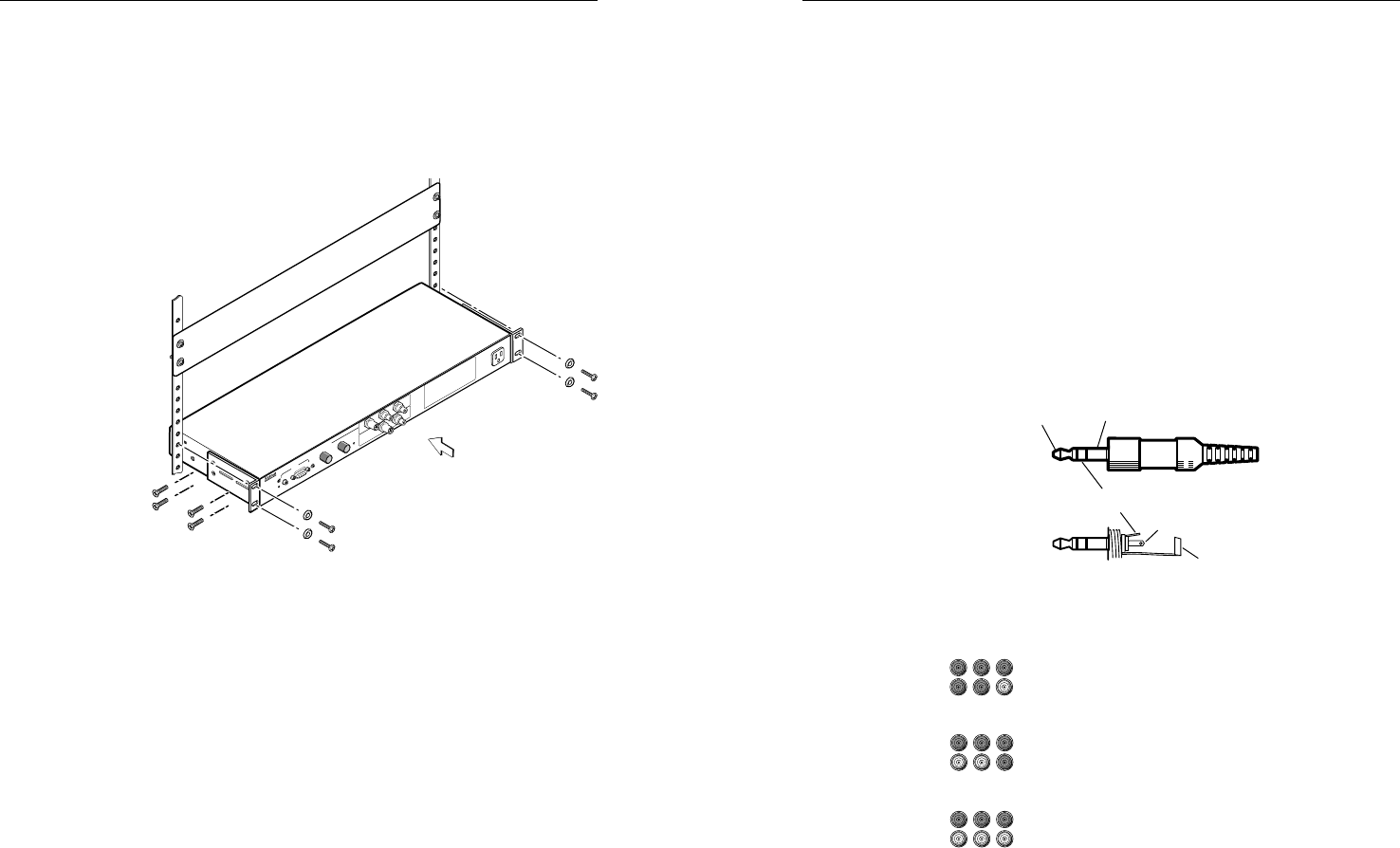
Rack mounting
1. Attach the through-desk/rack mounting brackets to the
interface with the provided machine screws, as
shown below.
2. Attach the interface to the rack with the provided
machine screws.
R
G
B
1
3
8
x
i
IN
P
U
T
S
A
U
D
IO
A
N
A
L
O
G
U
N
S
W
I
T
C
H
E
D
6
0
0
W
A
T
T
S
M
A
X
.
M
IN
/
M
A
X
M
B
C
P
O
W
E
R
U
N
IV
E
R
S
A
L
IN
T
E
R
F
A
C
E
W
/A
D
S
P
Rack mounting


