


RGB 400
xixi
xixi
xi Series Installation Guide
RGB 400
xixi
xixi
xi Series Installation Guide
Dimensions and Templates
RGB 464
xixi
xixi
xi
, RGB 474
xixi
xixi
xi
, RGB 468 M
xixi
xixi
xi
, RGB 478 M
xixi
xixi
xi
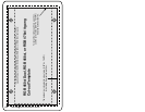
Cut-out Template
A-3
The light gray area represents the layout of the
electrical box (3.75"H x 5.60"W) against the rear of the
RGB 464
xi,
RGB 474xi, RGB 468 Mxi, or RGB 478 Mxi
front panel.
The dashed line indicates the cut-out area
(3.95"H x 5.80"W) for installing
the electrical wall box.
To install the interface
without
a wall box,
use the cut-out area (2.80"H x 5.50" W)
indicated by the dotted line.
RGB 464
xi,
RGB 474xi, 468 Mxi, or 478 Mxi 3-gang
Cut-out Template
A-2
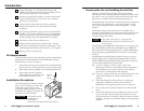
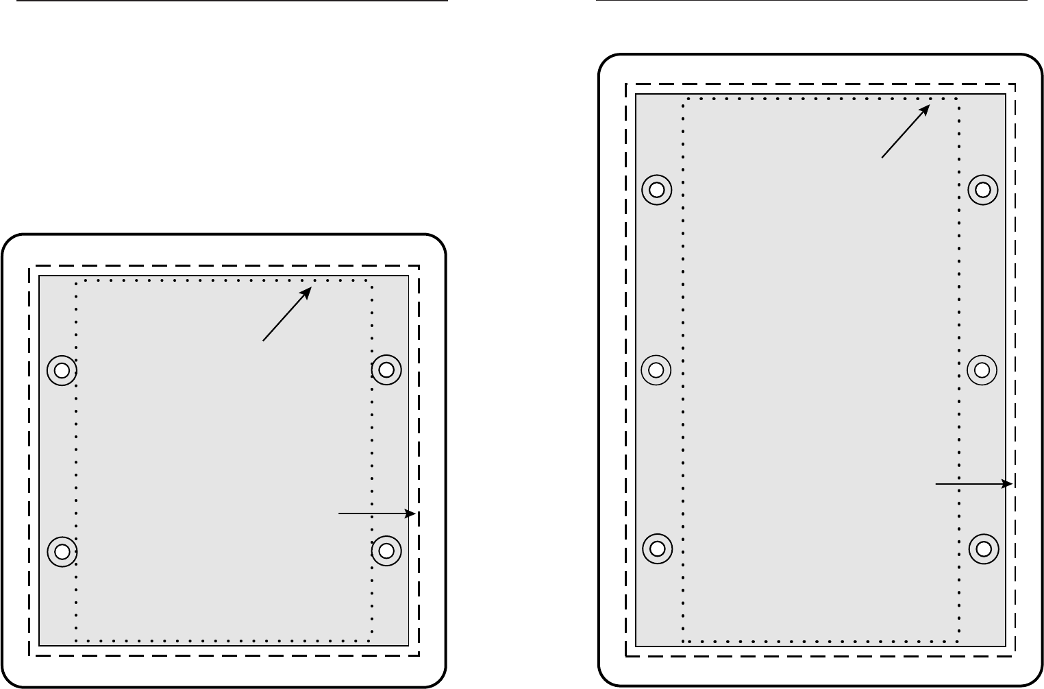
Cut-out Templates
All the templates in this section are actual size. Also, they
all include the recommended 0.1” (0.25 cm) clearance on all
sides of the electrical wall box to allow room for the raised
areas surrounding the knockouts.
The dashed line in each template indicates the cut-out area
for installing a wall box. If you plan to install the interface
without a wall box, use the smaller cut-out area indicated by
the dotted lines.
Use the following templates as a guide for cutting a hole in a
wall or furniture for the 2-, 3-, and 4-gang size electrical
boxes in order to install the appropriate interface.
RGB 460
xi, xi,
xi, xi,
xi,
RGB 472
xixi
xixi
xi
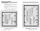
Cut-out Template
The light gray area represents the layout of the
electrical box (3.75"H x 3.75"W) against the rear
of the RGB 460
xi,
or RGB 472xi front panel.
The dashed line indicates the cut-out
area (3.95"H x 3.95"W) for installing
the electrical wall box.
To install the interface
without
a wall box,
use the cut-out area (3.00"H)
indicated by the dotted line.
RGB 460
xi,
or RGB 472xi 2-gang
Cut-out Template