


RGB 400
xixi
xixi
xi Series Installation Guide
RGB 400
xixi
xixi
xi Series Installation Guide
Introduction
3
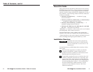
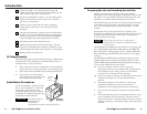
2.5"
RGB 464xi
(Example)
RGB 464
xi
INPUT
B
U
F
F
E
R
E
D
L
O
C
A
L
M
O
N
IT
O
R
H
. S
H
IF
T
M
IN
/
M
A
X
A
U
D
I
O
V
ID
E
O
S
-V
ID
E
O
A
U
D
I
O
HIGH
Z
75
N
E
T
W
O
R
K
L
R
Installation
Cable
Conduit
2
3
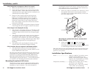
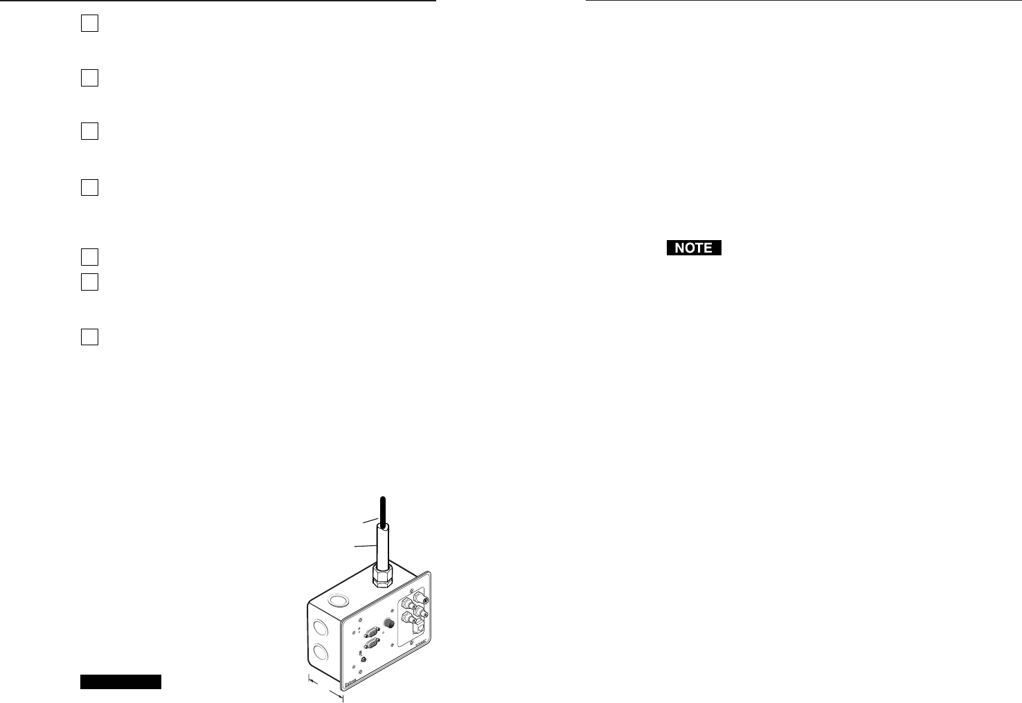
Attach the cables. See “Front panel features and
cabling” and “Rear panel features and cabling” in the
user’s manual specific to your product.
4
Set the rear panel DIP switches. Use the “Rear panel
features and cabling” section in the user’s manual
specific to your product.
5
Connect power cords and turn on the projector/
monitor and audio device, the interface, and the
computer.
6
The picture should now appear, and sound should be
audible. If not, ensure that all devices are plugged in
and receiving power. Check the cabling and the DIP
switch settings, and make adjustments as needed.
7
Disconnect power from all the devices.
8
Mount the interface into the electrical box. See the
sections on “Mounting the optional AAP device” and
“Mounting the interface to the wall box” in this guide.
9
Restore power to the devices.
UL Requirements
The following Underwriters Laboratories (UL) requirements
listed pertain to the installation of the RGB 400xi series of
interfaces into a wall or furniture.
1. These units are not to be connected to a centralized DC
power source or used beyond their rated voltage range.
2. These units must be installed in UL listed junction boxes.
3. These units must be installed
with conduit in accordance with
the National Electrical Code.
Installation Procedures
All of the interfaces can be mounted
into a wall or furniture. Follow the
instructions appropriate to the
mounting option you have selected.
Templates for optional faceplates are
not detailed in this manual.
CAUTION
The interface must be
installed into an
Underwriters
Laboratories (UL) approved electrical wall box.
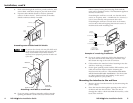
Preparing the site and installing the wall box
Choose a location that will allow cable runs without
interference. Allow enough depth for both the wall box and
the cables. You may need to install the cables into the wall,
furniture, or conduits before installing the interface.
The installation must conform to national and local electrical
codes and to the equipment’s size requirements. Actual-
size cut-out templates are provided in appendix A of this
manual.
Installation using a UL listed wall box (available from
Extron) is recommended for most mounting options, but the
included mud rings can be used instead. All wall boxes
must be at least 2.50” deep.
Before using the mud rings, verify that the
installation will conform to national and local
electrical codes.
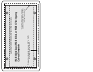
The RGB 460xi and RGB 472xi will install in a two-gang wall
box, the RGB 464xi, RGB 474xi, RGB 468 Mxi, and RGB 478
Mxi will install in a three-gang wall box, and the RGB 460xi
Dual, RGB 468xi, and RGB 478xi will install in a four-gang
wall box.
The RGB 468xi and RGB 478xi faceplates accept up to four
single height Extron Architectural Adapter Plates (AAPs)
and the RGB 468 Mxi and RGB 478 Mxi faceplates accept up
to four single height Extron mini-AAPs.
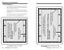
1a. If you are using a wall box, make a 100% size
photocopy of the cut-out template that corresponds to
the faceplate you are using, and cut out the center
portion of it as indicated on the template.
1b. If you are using a mud ring, use the template that came
with the mud ring. Cut out the indicated center
portion.
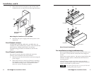
2. Place the template (or the wall box or mud ring)
against the installation surface, and mark the
guidelines for the opening on the wall or furniture.
3. Cut out the wall/furniture material from the marked
area.
4. Check the opening size by inserting the wall box, mud
ring, or interface into the opening. The box or mud
ring (if used) and/or interface should fit easily into the
opening. Enlarge or smooth the edges of the opening if
needed.