


RGB 400
xixi
xixi
xi Series Installation Guide
RGB 400
xixi
xixi
xi Series Installation Guide
Installation, cont’d
76
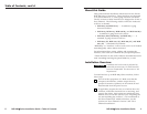
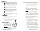
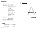
3. Mount the interface’s faceplate to the wall box with
machine screws, as shown in the following illustration.
Mounting the interface to the wall box
4. Reconnect the power supply and restore power to the
equipment.
Euro Channel versions
The RGB 460xi, RGB 468xi, RGB 472xi, and RGB 478xi are
available in a Euro Channel (EC) version. The front and rear
panel features, cabling requirements, and testing/
troubleshooting procedures are identical to the non-EC
models.
Euro Channel installation
Once the EC interface has been cabled and tested, the
interface can be installed in the Euro Channel.
1. Remove power from the interface by disconnecting the
power supply.
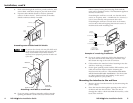
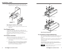
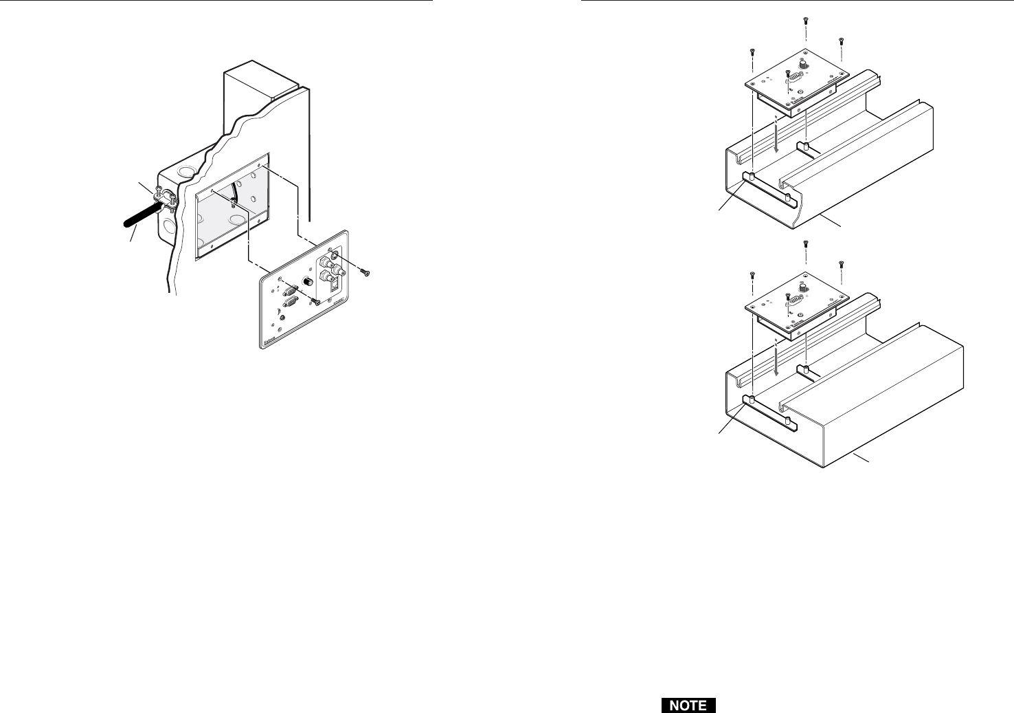
2. Mount the interface to the Euro Channel by attaching
the faceplate to the two rear backing plates using the
four #4-40 mounting screws. See the illustrations
below for various mounting examples.
Euro Channel installation
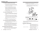
Pre-installation testing/troubleshooting
Before installing the interface into the wall or furniture, test
the system to verify that the connections and settings are
correct.
Apply power to the interface. The power/signal LED on the
interface will light yellow to indicate that the interface is
receiving power.
If the LED does not light, check the wiring at both the
interface and the power supply, and ensure that the power
supply is connected to a power source.
If the input signal has sync on green, the LED will
not change from yellow to green
Euro Channel
Backing Plate
Euro Channel
Backing Plate
RGB 420
xi
I
N
P
U
T
H. SHIFT
MIN/MAX
AUDIO
N
O
M
O
N
IT
O
R
M
O
N
IT
O
R
RGB 420
xi
I
N
P
U
T
H. SHIFT
MIN/MAX
AUDIO
N
O
M
O
N
IT
O
R
M
O
N
IT
O
R
Installation
Cable
Cable
Clamp
RGB 464
xi
I
N
P
U
T
M
O
N
I
T
O
R
H
.
S
H
I
F
T
M
I
N
/
M
A
X
A
U
D
I
O
V
I
D
E
O
S
-
V
I
D
E
O
A
U
D
I
O
L
/
M
O
N
O
R
M
O
N
I
T
O
R
N
O
M
O
N
I
T
O
R
Extron RGB 464xi
(Example)