


RGB 400
xixi
xixi
xi Series Installation Guide
RGB 400
xixi
xixi
xi Series Installation Guide
Installation, cont’d
5
Flush with
Wall Surface
Screws or Nails
Wall Stud
Wall Box
4
Installation
Cable
Cable
Clamp
Wall Stud
Foil
Shield
Screws or Nails
Screw
Braided
Shield
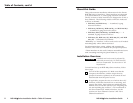
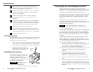
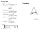
5. Feed cables through the wall box punch-out holes, and
secure them with cable clamps to provide strain relief.
6. Exposed cable shields (braids or foil) are potential
sources of short circuits. Trim back and/or insulate
shields with heat shrink, if needed.
Grounding outer braided and foil shields
To prevent short circuits, the outer foil shield can be
cut back to the point where the cable exits the cable
clamp. Both braided and foil shields should be
connected to an equipment ground at the other end
of the cable.
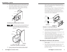
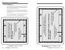
Attaching a wall box to a wall stud
7a. If you are using a wall box, insert the wall box into the
opening, and attach it to the wall stud/furniture with
nails or screws, leaving the front edge flush with the
outer wall or furniture surface. The illustration applies to
all sizes of wall boxes.
If attaching the wall box to wood, use four #8 or #10
screws or 10-penny nails. A minimum of 1/2 inch (1.3
cm) of screw threads must penetrate the wood.
If attaching the wall box to metal studs or furniture,
use four #8 or #10 self-tapping sheet metal screws or
machine bolts with matching nuts.
Example of a mud ring installation
7b. If you are using a mud ring, follow the directions, if
any, that came with the mud ring to attach the clips
that fasten the ring to the wall or furniture.
8. Cable and test the interface before fastening it into the
wall box, mud ring, or furniture.
9. Set the gain/peaking switch and the DIP switches, and
cable and test the interface before fastening the
interface into the wall box. The switches and cables
will be inaccessible after installation. See the section
on “Rear panel features and cabling” in the user’s
manual specific to your product.
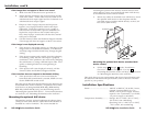
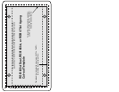
Mounting the interface to the wall box
1. Remove power from the interface by disconnecting the
power supply.
2. Place the interface through the opening in the wall or
furniture and into the wall box. Take care not to
damage the cables, which fit behind the interface, at the
back of the wall box.
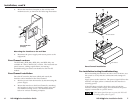
Detail A
0.75" #6-32 Screw
Backing Clip
Backing Clip
Sheet Rock
Sheet Rock
Mounting Bracket
Mounting Bracket
Detail B
1.25" #6-32 Screw
Backing Clip can
be in either orientation.
See Detail A or Detail B.
Extron RGB 464
xi
(Example)
R
G
B
4
6
4
x
i
INPUT
M
O
N
I
T
O
R
H. SHIFT
M
IN/MA
X
AUDIO
VIDE
O
S-VIDEO
A
UDIO
L
/MO
NO R
M
ONIT
OR
NO
M
ONITOR