


RGB 580xi • Installation and Setup
RGB 580xi • Installation and Setup
Installation and Setup, cont’d
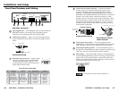
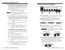
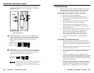
Rear Panel Features and Cabling
1
AC power connector — Connect a standard IEC AC power
cord here for power input (100 VAC to 240 VAC, 50/60 Hz) to
the internal, autoswitching power supply.
2
BNC output connectors — Connect coaxial cables from a
display device to these BNCs for one RGBHV, RGBS, or
RGsB/RsGsBs video output as follows:
3
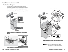
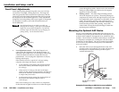
Audio output connector — Cable an audio device to the
interface via this female 5-pole captive screw connector. Wire
the male connector as shown below.
CAUTION
Connect the sleeve to ground (GND). Connecting
the sleeve to a negative (-) terminal will damage the
audio output circuits.
Unbalanced Output
Tip
See Caution
Sleeve (s)
Tip
See Caution
Balanced Output
Tip
Ring
Sleeve (s)
Tip
Ring
LR
LR
4
RS-232 connector — Connect an RS-232 device (control system
or PC computer) to this female 3-pole captive screw connector
for two-way RS-232 communication. Software for RS-232
control is included with the interface. See the chapter three
section, Remote Control, for information on how to install and
use the control software and SIS commands. Wire the male
connector as shown below.
Transmit
Receive
Ground
Tx
Rx
RS-232
2-9
100-240 0.5A MAX.
50/60 Hz
OUTPUTS
R
H
G
V
B
AUDIO RS-232
TxRx
1
2
4
3
RGBSRGBHV RGsB (Sync on Green)
RsGsBs (output only if input is RsGsBs)
RGB
H/HV
V RGB
H/HV
V RGB
H/HV
V
2-8
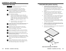
1 — DDSP (Digital Display Sync Processing) — This feature
may be necessary for digital display devices such as LCD,
DLP (digital light processing) and plasma displays. Use this
option if the image is not displayed properly after other
options, such as serration pulse and vertical sync pulse
width, have been explored.
On — The interface uses DDSP instead of ADSP.
DDSP does not process the sync signal.
DDSP disables the horizontal shifting control.
Off — The interface performs sync processing operations,
such as centering, with ADSP.
2 — Serr (serration pulse) — Many LCD and DLP projectors
and plasma displays must have serration pulses removed
from the sync signal in order to display properly. Flagging
or bending at the top of the video image is a sign that the
serration pulses should be removed.
On — The interface outputs serration pulses in the vertical
sync interval.
Off — The interface does not output serration pulses.
3 — SOG (sync on green)
On — The interface outputs sync on green.
Off — The interface outputs separate horizontal and
vertical sync (on the H and V connectors) for
RGBHV.
4 — V-Sync Width (vertical sync pulse width) — For some
digital display devices, if no picture appears, the picture
cuts in and out, or the picture is scrambled, try adjusting
the output vertical sync pulse width or switching from
ADSP to DDSP.
On — The vertical sync pulse is narrow.
Off — The vertical sync pulse is wide.
5 — Neg Sync — This switch controls sync polarity.
On — Both the horizontal and the vertical sync signals are
forced to negative polarity on output.
Off — Output sync polarity follows (is the same as) input
polarity.
6 — Comp Sync — This switch controls composite sync output.
On — The interface outputs combined horizontal and
vertical sync for RGBS.
Off — The interface outputs RGBHV or RGsB video.