


RGB 580xi • Installation and Setup
RGB 580xi • Installation and Setup
Installation and Setup, cont’d
RGB 580
xi
CCSI AAP
Cable Cubby
CC AAP VGA connector
CC AAP Audio connector
INPUT
SELECT
H. SHIFT
1
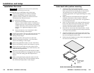
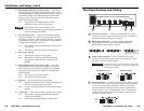
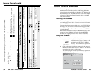
Power/signal LED — This LED lights
• amber to indicate that the CC AAP device is receiving
power.
• green to indicate that an active sync signal is present at the
input and that the CC AAP device is receiving power.
The LED flashes green whenever the minimum and
maximum limits of the horizontal shift control (H. shift)
have been reached.
2
Horizontal shift control knob (H. shift) — While viewing the
displayed image, rotate this control to move the image to the
right or left on the screen. The power/signal LED flashes green
whenever the minimum and maximum limits of this control are
reached.
DDSP disables the horizontal shifting control.
3
Input select button — Pressing this button results in contact
closure between pins A and B of the contact closure control
connector on the front panel of the RGB 580xi.
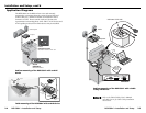
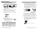
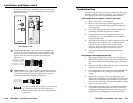
Cabling the Cable Cubby AAP Devices
Extron’s various CC AAP devices for the RGB 580xi come with
rear panel connectors that may require cabling.
Although the control cable/LED cable assembly comes
prewired to the captive screw connectors, any
subsequent connector replacement will require the
following cabling instructions.
2-14
2
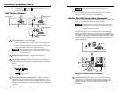
LED connector (J2) — Insert wires into and tighten the screws
on the 3.5 mm, 3-pole captive screw connector. This connector
is used for powering the green and amber LEDs. Wire the
connector as shown in the following illustration.
3
Audio output connector (J3) — Insert wires into and tighten the
screws on the 3.5 mm, 3-pole captive screw connector. This
connector is used for unbalanced stereo audio output. Wire the
connector as shown in the following illustration.
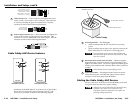
Cable Cubby AAP Device Features
INPUT
SELECT
SHIFT
SHIFT
RGB 580xi
RGB 580xi
2
1
2
3
1
RGB 580xi CCS AAP
RGB 580xi CCSI AAP
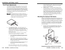
Installation of the RGB 580xi CC AAP devices in a Cable Cubby
allows the VGA and audio cable connectors of the CC AAP
device to be accessible, as shown in the following diagram.
Horizontal shift + (green)
Horizontal shift ground (gray)
Horizontal shift
– (brown)
Contact closure
+ (light blue)
Contact closure
– (purple)
Control
1 2 3 4 5
Green LED (pink)
LED ground (yellow)
Amber LED (orange)
LED
1 2 3
Audio right (red)
Audio ground (black)
Audio left (white)
R+
L+
3 2 1
2-15