


RGB 580xi • Installation and Setup
Installation and Setup
RGB 580xi • Installation and Setup 2-7
4
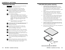
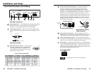
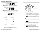
Contact closure control connector — Connect an optional
contact closure device to this female 5-pole captive screw
connector. Making contact closure between pins A and B
transmits a channel signal through the RS-232 port. Extron’s
RGB 580xi I AAP and RGB 580xi SI/CCSI AAP (see “AAP Device
Features” and “Cable Cubby AAP Device Features” in this
chapter) provide a one-button contact closure operation. Wire
the male connector as shown below on the left. Extron’s VGA
and control cable assembly (see chapter A, “Cables”, for part
numbers) comes with the male control connector prewired as
shown below on the right.
Contact closure wiring
Prewired male control
cable connector
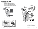
5
Video output: level control — This control adjusts picture
brightness by compensating for signal amplitude loss caused by
cable resistance. See Front Panel Adjustments in this chapter.
6
Video output: peaking control — This control adjusts picture
sharpness by compensating for cable capacitance caused by long
cable runs. See Front Panel Adjustments in this chapter.
7
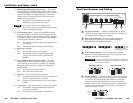
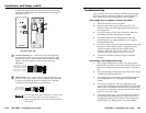
DIP switches — This bank of DIP switches, as illustrated below,
controls DDSP (Digital Display Sync Processing), serration pulse
output, SOG (sync on green) output, vertical sync width, sync
polarity, and composite sync output. Moving a switch up sets it
to On and moving it down sets it to Off.
SOG
SERR
DDSP
V-SYNC WIDTH
NEG SYNC
COMP SYNC
The default for all DIP switches is Off (down).
Contact Closure
Contact closure
Contact closure
5VDC
Ground
5VDC
CONTROL
AB
C
D
E
Prewired male control connector
Male VGA connector
5
1
15
11
6
10
Pin Description
Wire ID
Pin Description Wire ID
15-pin HD male pinout table
1 red signal red coax
2 green signal green coax
3 blue signal blue coax
4 horizontal shift + green wire
5 horizontal shift
— brown wire
6 red coax ground red coax shield
7 green coax ground green coax shield
8 blue coax ground blue coax shield
9 LED red orange wire
10 horizontal sync ground black coax shield
10 vertical sync ground yellow coax shield
10 audio ground black wire
10 LED ground yellow wire
10 shift ground gray wire
11 audio right red wire
12 audio left white wire
13 horizontal sync black coax
14 vertical sync yellow coax
15 LED green pink wire
Front Panel Features and Cabling
SOG
SERR
DDSP
V-SYNC WIDTH
NEG SYNC
COMP SYNC
INPUTS
RGB 580
xi
ANALOGAUDIO
CONTROL
VIDEOOUTPUT
LEVEL
A B C D E
PEAKING
1
2
3
5
4
7
6
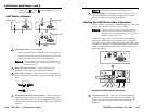
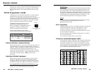
RGB 580xi front panel
1
Power/signal LED — This LED lights amber to indicate that the
RGB 580xi interface is receiving power, and lights green to
indicate it is receiving both power and an input signal.
2
Audio input connector — Plug a 3.5 mm stereo plug into this
jack for unbalanced audio input. Wire the male plug as shown
below.
Tip (L) Sleeve (GND)
Tip (L)
Ring (R)
Sleeve (GND)
Audio input wiring
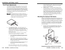
3
RGB video input connector — Attach a cable
from the computer source to the RGB 580xi
via this 15-pin HD female connector. The
15-pin HD male connector pin locations and
pinout table are shown here.
2-6