


RGB 580xi • Installation and Setup
RGB 580xi • Installation and Setup
Installation and Setup
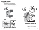
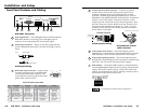
Under-desk/-table/-podium mounting
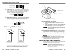
1. Attach the under-desk mounting brackets
(part #70-077-01) to the interface with the six machine
screws (provided in the mounting kit), as shown below.
This procedure may also apply to table or podium
mounting applications. See “Application Diagrams” in this
chapter.
2. Hold the interface with attached brackets against the
underside of the desk or other furniture. Mark the
location of holes for screws on the desk. See appendix B
for mounting dimensions.
3. Drill 1/4" (6.4 mm) deep, 3/32" (2.38 mm) diameter pilot
holes in the table or desk at the marked screw locations
from the underside or inside (concealed side) of the
furniture, where the interface will be located.
4. Insert the four wood screws into the pilot holes. Fasten
each screw into the installation surface until just less than
1/4" of the screw protrudes.
5. Align the installed screws with the slots in the mounting
brackets, and place the interface against the surface, with
the screws through the bracket slots.
6. Slide the interface slightly forward or back, then tighten all
four screws to fasten it in place.
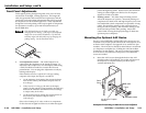
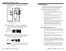
Mounted under
a desk, table or
podium
SO
G
SERR
DD
SP
V-S
YNC
W
IDTH
NEG SYNC
C
O
M
P S
YNC
INPUTS
RGB 580
xi
ANALOG
AUDIO
CONTROL
V
ID
E
O
O
U
T
P
U
T
LEVEL
A B C D E
PEAKING
Under-desk mounting of the RGB 580xi
2-3
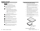
Installation Overview
CAUTION
Installation and service must be performed by
authorized personnel only.
To install and set up an RGB 580xi, follow these steps:
1
Turn all of the equipment off. Make sure that the
computer, the RGB 580xi, and the output devices
(projector/monitor, speakers) are all turned off and
disconnected from the power source.
2
For under-desk mounting:
A. Determine the installation location: table, desk,
podium, or other suitable location. If Architectural
Adapter Plates are to be connected to the interface,
consider where they will be located in relation to the
interface. See “Application Diagrams” in this
chapter.
B. Mount the interface. See “Under-desk/-table/
-podium mounting” in this chapter.
3
Attach output cables to the rear panel of the interface and
to the output devices. See “Rear Panel Features and
Cabling” in this chapter.
4
Attach input cables to the input devices and to the
interface’s front panel connectors. See “Front Panel
Features and Cabling” in this chapter.
5
Set the front panel DIP switches. Use the “Front Panel
Features and Cabling” section of this chapter as a guide.
6
Connect power cords and turn on the output devices
(projector/monitor, speakers), the remote interface, and
audio and video input devices.
7
The picture should appear, and sound should be audible.
If not, ensure that all devices are plugged in and receiving
power. Check the cabling and make adjustments as
needed.
8
While watching the display, adjust the video level and
peaking by using the rotary Level and Peaking controls.
See “Front Panel Adjustments” in this chapter.
2-2