


SW2 VGA DA2 AF R • Installation and Operation
SW2 VGA DA2 AF R • Installation and Operation
Installation and Operation, cont’d
2-10 2-11
8
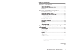
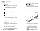
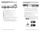
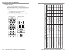
Autoswitching/Contact closure connector (AS/REMOTE) —
Connect a contact closure control device to the left three pins of
this 3.5 mm, 5-pole captive screw connector.
• Pin 1 selects input 1 when connected to ground.
• Pin 2 selects input 2 when connected to ground.
• Pin 3 connects to the ground wire.
1
2
I
A
S
L R
AS/REMOTE
Contact Closure Control
Jumper pins 4 & 5 fo
r
autoswitching
• Pins 4 and 5 if jumpered/shorted together will turn the auto-
switching mode on. When the auto-switching mode is on,
the switcher automatically switches to the input that has an
active sync signal.
If both inputs have an active sync signal present, the
highest input, input 2, will be used, and the input 2
indicator LED will light. If no active sync signal is present,
neither input indicator LED will light.
Auto-switching overrides manual input selection. If
auto-switching is on, contact closure and front panel
input selection will be disabled.
• If pins 4 and 5 are not connected, manual switching is
enabled. Selections can be made via the front panel
selection switches and the contact closure device.
If no active sync signal is present, the input 2 indicator LED
will still light.
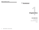
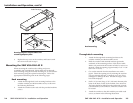
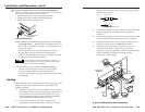
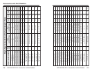
Cabling
Attach cables to the switcher as detailed in the steps below. The
diagram in this section shows how the system looks when
cabling is finished.
1. Attach the VGA/SVGA/XGA computers’ output cables to
the switcher via the 15-pin HD female input connectors. If
the computers will provide the audio input, VGA with
audio combination cables, such as the Extron VGA HRA
series (#26-490-01 to #26-490-04), can be used.
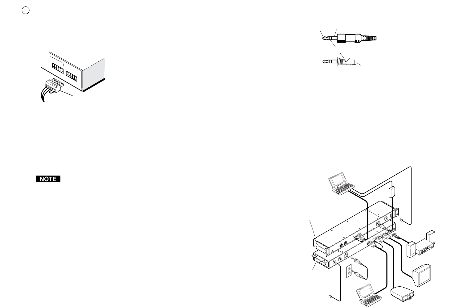
2. Connect the cables from the stereo audio sources
(computers or other devices such as CD players or tape
decks) to the audio input jacks. The audio plug should be
wired as shown below.
T
ip (+) Sleeve (Gnd)
Tip (L, +)
Ring (R, -)
Sleeve (Gnd)
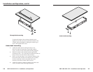
3. Connect VGA cables from the switcher’s 15-pin HD female
output connectors to the display devices (projectors,
monitors).
4. Connect the speakers’ or other audio output device’s cable
to the switcher’s audio output captive screw connector.
5. Attach the contact closure device to the left three pins of
the 5-pole captive screw AS/REMOTE connector.
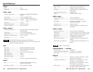
6. Connect power cords and turn on the devices in the
following order: display and audio output devices
(projectors, monitors, speakers), contact closure controller,
SW2 VGA DA2 AF R switcher, and input devices
(computers, audio sources).
A typical SW2 VGA DA2 AF R installation
1
0
0
-
2
4
0
5
0
/
6
0
H
z
0
.
5
A
I
N
P
U
T
1
12
A
S
A
S
/R
E
M
O
T
E
O
U
T
P
U
T
S
A
B
U
N
S
W
I
T
C
H
E
D
1
0
0
-
2
4
0
0
.
5
A
M
A
X
.
A
U
T
O
S
W
IT
C
H
A
C
T
IV
E
S
W
2
V
G
A
D
A
2
A
F
R
1
2
I
N
P
U
T
2
Mounted under
a Desk
Rear
Front
Through-desk or
Rack Mounted
Power
AC Power
LBC w/ Audio
Cable
Network
Connection
Network
Connection
LCD Projector
Laptop or VGA Computer
Laptop
Monitor
Stereo Audio