


SW2 VGA DA2 AF R • Installation and Operation
SW2 VGA DA2 AF R • Installation and Operation
Installation and Operation, cont’d
2-9
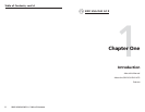
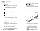
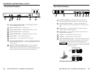
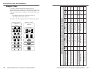
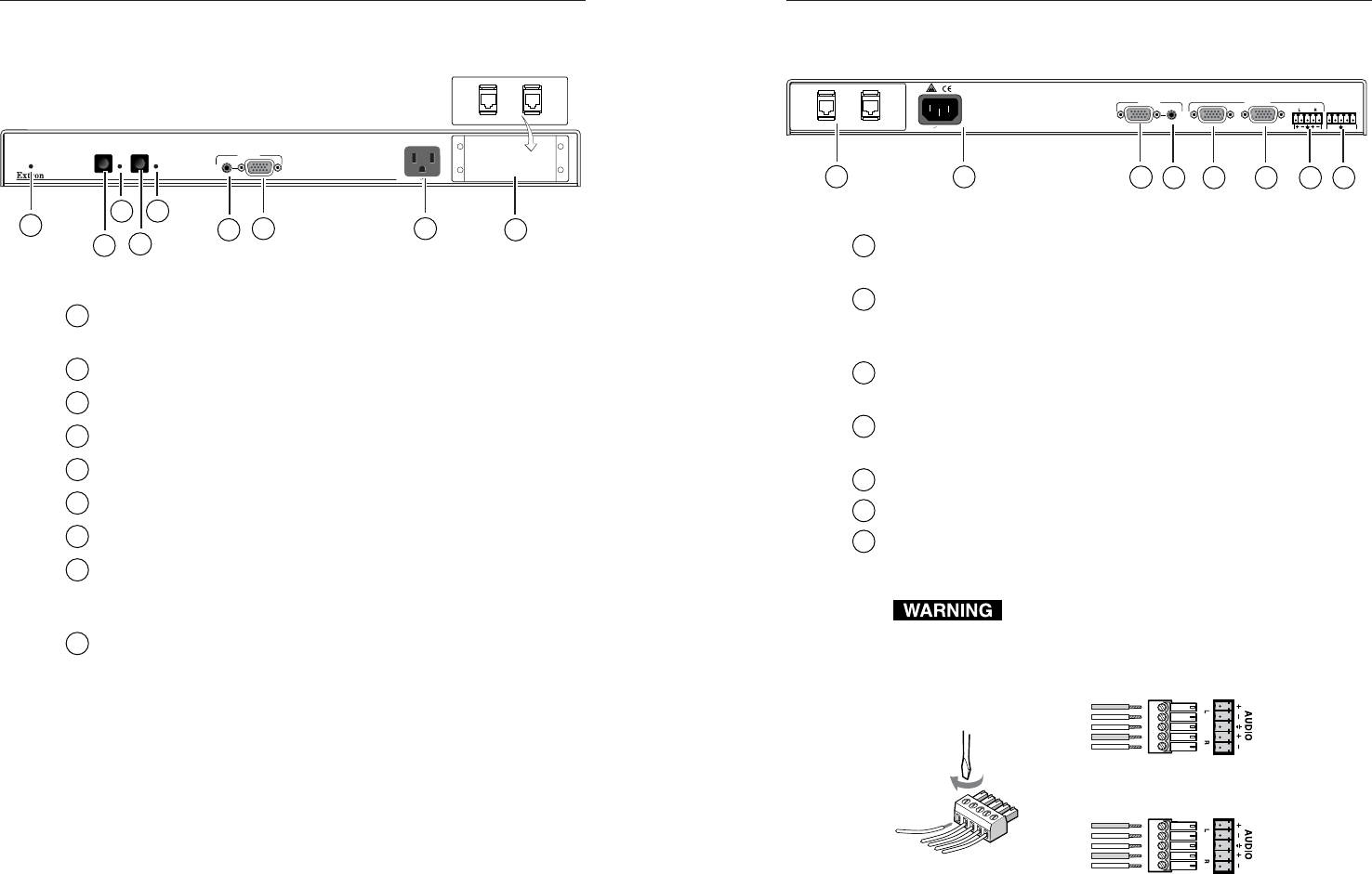
Front Panel Features
1
Auto-switching indicator LED — This LED lights when the
auto-switching feature is active.
2
Input 1 selection switch — Selects input 1
3
Input 1 indicator LED — This lights when input 1 is active.
4
Input 2 selection switch — Selects input 2
5
Input 2 indicator LED — This lights when input 2 is active.
6
Input 2 audio — 3.5 mm female audio jack
7
Input 2 video — 15-pin HD female VGA connector
8
AC power output connector — An unswitched standard IEC AC
power connector allows you to connect a peripheral device that
requires power.
9
Optional architectural adapter plates — Up to two adapter
plates for pass-through audio/video connections can be
attached at one time to the switcher. See the “Installing Adapter
Plates” section in this chapter for installation instructions.
2-8
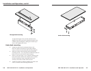
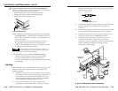
1
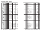
Cable access opening — Cables attached to the A/V pass-
through architectural adapter plates exit the enclosure here.
2
AC power input connector — Connect a standard IEC AC
power cord here for power input (100VAC to 120VAC, 50/60
Hz).
3
Input 1 video — 15-pin HD female VGA connector (Input 2
video is located on the front panel.)
4
Input 1 audio — 3.5 mm female audio jack (Input 2 audio is
located on the front panel.)
5
Output A — 15-pin HD female VGA connector
6
Output B — 15-pin HD female VGA connector
7
Stereo audio output connector — Balanced or unbalanced audio
can be output via this 3.5 mm, 5-pole captive screw connector.
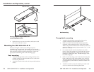
The audio output cable should be wired as shown below.
Connect the sleeve to ground (GND). Connecting
the sleeve to a negative (-) terminal will damage the
audio output circuits.
Unbalanced Output
Tip
See Warning
Sleeve (s)
Tip
See Warning
Balanced Output
Tip
Ring
Sleeve (s)
Tip
Ring
Wiring the audio output connector
Rear Panel Features
UNSWITCHED
100-240 0.5A MAX.
AUTO SWITCH
ACTIVE
SW2 VGA DA2 AF R
12
INPUT 2
1
2
3
4
6
7 8
9
5
100-240 50/60 Hz 0.5A
INPUT 1
12 AS
AS/REMOTE
OUTPUTS
AB
1
2
3
4 5 6 7 8