


SW2 VGA DA2 AF R • Installation and Operation
SW2 VGA DA2 AF R • Installation and Operation
Installation and Operation, cont’d
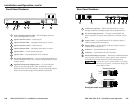
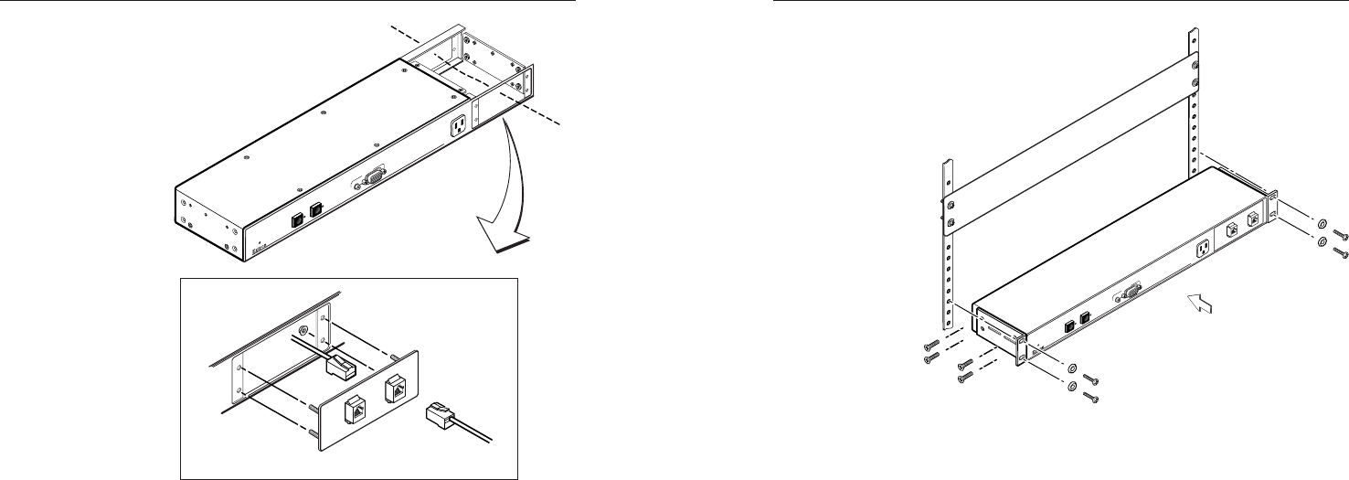
Adapter Plate
Tighten nuts
securely
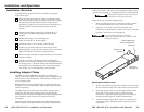
Front or Rear AAP Installation
Cable Routing
U
N
S
W
I
T
C
H
E
D
1
0
0
-2
4
0
0
.5
A
M
A
X
.
A
U
T
O
S
W
I
T
C
H
A
C
T
I
V
E
S
W
2
V
G
A
D
A
2
A
F
R
1
2
I
N
P
U
T
2
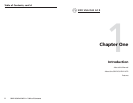
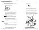
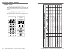
Routing adapter output cables and
attaching adapter plate
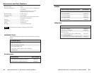
6. Replace the top cover on the switcher, and fasten it with
the screws removed in step 2.
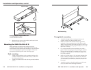
Mounting the SW2 VGA DA2 AF R
When mounting the switcher, take cabling and power
availability into consideration. Select either rack or through-
desk mounting using the included mounting kit, or select under-
desk mounting using the optional mounting kit. Follow the
appropriate installation guide on the following pages.
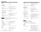
Rack mounting
1. Attach the through-desk/rack mounting brackets to the
switcher with the provided machine screws, as shown in
the following illustration.
2. Attach the switcher to the rack with the provided machine
screws.
2-4
U
N
S
W
I
T
C
H
E
D
100
-24
0 0.5
A MAX.
A
U
T
O
S
W
IT
C
H
A
C
T
IV
E
S
W
2
V
G
A
D
A
2
A
F
R
1
2
I
N
P
U
T
2
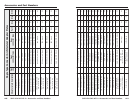
Rack mounting
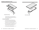
Through-desk mounting
1. Attach the through-desk mounting brackets to the
switcher with the provided machine screws.
2. Hold the switcher with attached brackets against the
underside of the mounting surface of the desk or table.
With a soft pencil mark the location of holes for screws on
the desk. Mark the opening, approximately 17.63” x 1.88”
(44.77 cm x 4.76 cm).
3. Cut out the material from the installation area with a
jigsaw. Check the opening size by inserting the switcher
part way through the hole. If needed, use a saw, file or
sandpaper to enlarge the hole. Smooth the edges of the
hole with sandpaper.
4. Drill 1/4” (6.4 mm) deep, 3/32” (2.38 mm) diameter pilot
holes in the desk or table at the marked screw locations.
The holes should be drilled from the underside or inside
(concealed side) of the furniture, where the switcher will
be located.
5. Attach the switcher to the desk with the provided wood
screws, as shown in the following illustration.
2-5