


YCS SW2 • Installation and Operation
Installation and Operation, cont’d
2-6
YCS SW2 • Installation and Operation
2-7
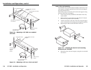
4. Repeat steps 2 and 3 on the other side of the YCS.
5. Hold the unit with the attached brackets against the
underside of the table or other furniture. On the mounting
surface, mark the location of the bracket’s screw holes.
6. Drill 3/32” (2 mm) diameter pilot holes, ¼” (6.3 mm) deep
in the mounting surface at the marked screw locations.
7. Insert #8 wood screws into the four pilot holes. Tighten
each screw into the mounting surface until slightly less
than ¼” of the screw head protrudes.
8. Align the mounting screws with the slots in the brackets
and place the unit against the surface, with the screws
through the bracket slots.
9. Slide the unit slightly forward or back, then tighten all four
screws to secure it in place.
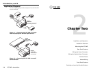
Projector mounting
To projector-mount the YCS SW2, three optional mounting kits
are available for use with the YCS SW2.
PMK 100 Mini Projector Mount Kit
The PMK 100 is a projector mounting kit (part # 70-217-01)
designed for use with Extron 1U high, quarter-rack width
products like the VersaTools products. It allows them to be
mounted near or on a projector support.
Follow these steps to projector-mount the YCS SW2 using the
PMK 100 kit:
1. If rubber feet were previously attached to the bottom of the
unit, remove them.
2. Remove the two screws from one side of the YCS. Retain
the screws for possible later reassembly.
3. Attach the projector mounting bracket to the side of the
unit, using the provided machine screws.
3
1
2
O
U
T
P
U
T
I
N
P
U
T
S
M
LS
103 V
L
R
A
B
LR
L
R
LR
1
2
3
L
R
4
A
U
X
/
M
I
X
M
O
N
O
A
U
D
I
O
I
N
P
U
T
S
P
R
E
A
M
P
M
L
C
/
R
S
-
2
3
2
P
O
W
E
R
12
V
.5A
M
A
X
3
1
2
O
U
T
P
U
T
I
N
P
U
T
S
M
LS
103
V
L
R
A
B
L
R
L
R
L
R
1
2
3
L
R
4
A
U
X
/
M
I
X
M
O
N
O
A
U
D
I
O
I
N
P
U
T
S
P
R
E
A
M
P
M
L
C
/
R
S
-
2
3
2
P
O
W
E
R
12V
.5
A
MAX
3
1
2
O
U
T
P
U
T
I
N
P
U
T
S
M
L
S
103 V
L
R
A
B
LR
L
R
L
R
1
2
3
L
R
4
A
U
X
/
M
I
X
M
O
N
O
A
U
D
I
O
I
N
P
U
T
S
P
R
E
A
M
P
M
L
C
/
R
S
-
2
3
2
P
O
W
E
R
12
V
.5A
M
A
X
M
M
X
32
V
G
A
A
O
U
T
P
U
T
1
2
1
3
O
U
T
P
U
T
2
2
1
3
Y
C
S
S
W
2
2
1
A
U
T
O
S
W
I
T
C
H
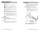
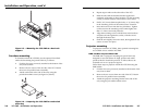
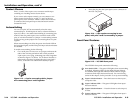
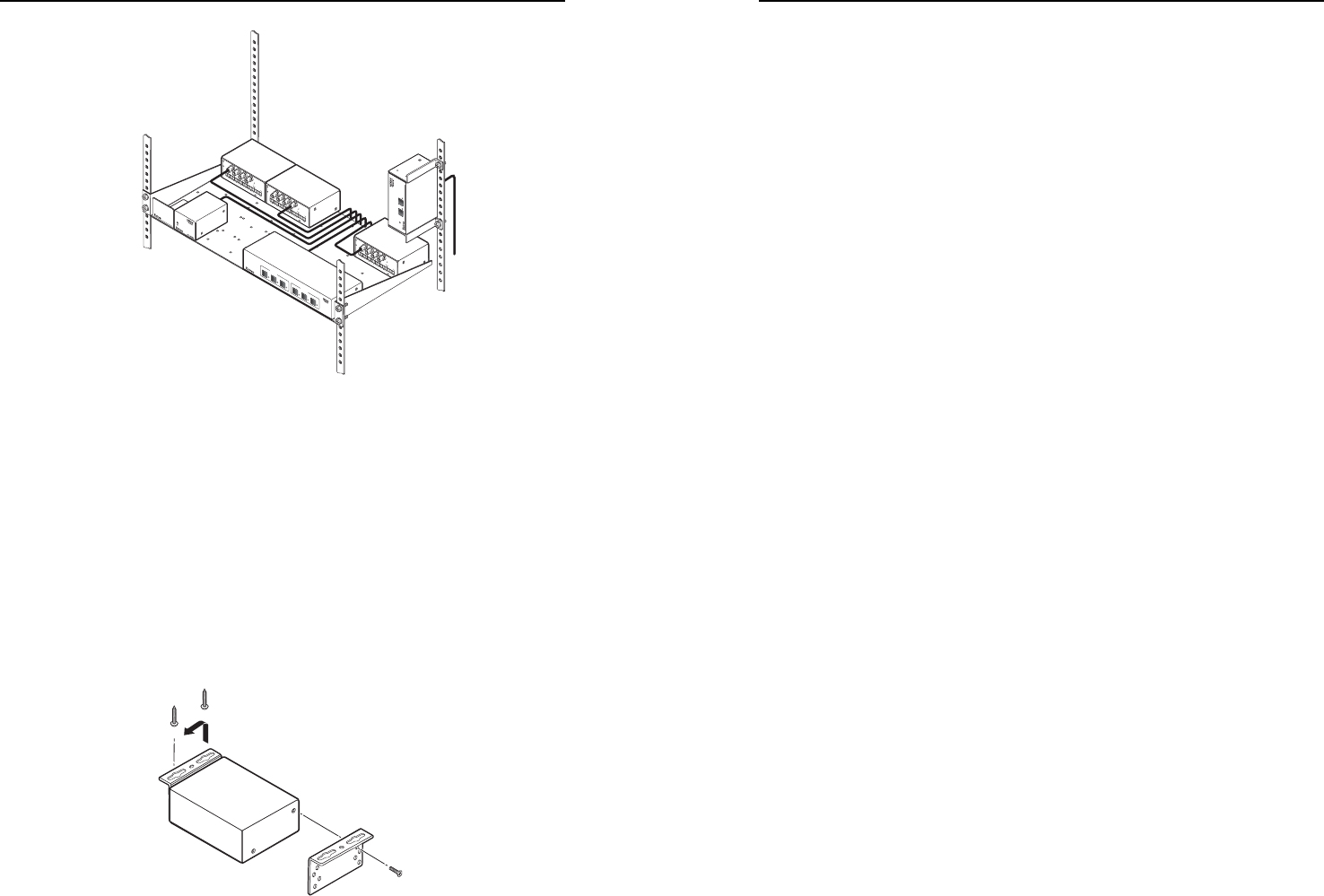
Figure 2-5 — Mounting the YCS SW2 to a back rack
support
Furniture mounting
To furniture-mount the YCS SW2, use the optional VersaTools
under-desk mounting kit (part #70-212-01), as follows.
1. If rubber feet were previously attached to the bottom of the
unit, remove them.
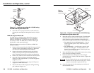
2. Remove the two screws from one side of the YCS. Retain
the screws for possible later reassembly.
3. Attach one bracket to the side of the unit, using the
provided machine screws (see fi gure 2-6, below).
Figure 2-6 — Preparing the YCS SW2 for under-desk
mounting