


YCS SW2 • Installation and Operation
Installation and Operation, cont’d
2-10
YCS SW2 • Installation and Operation
2-11
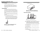
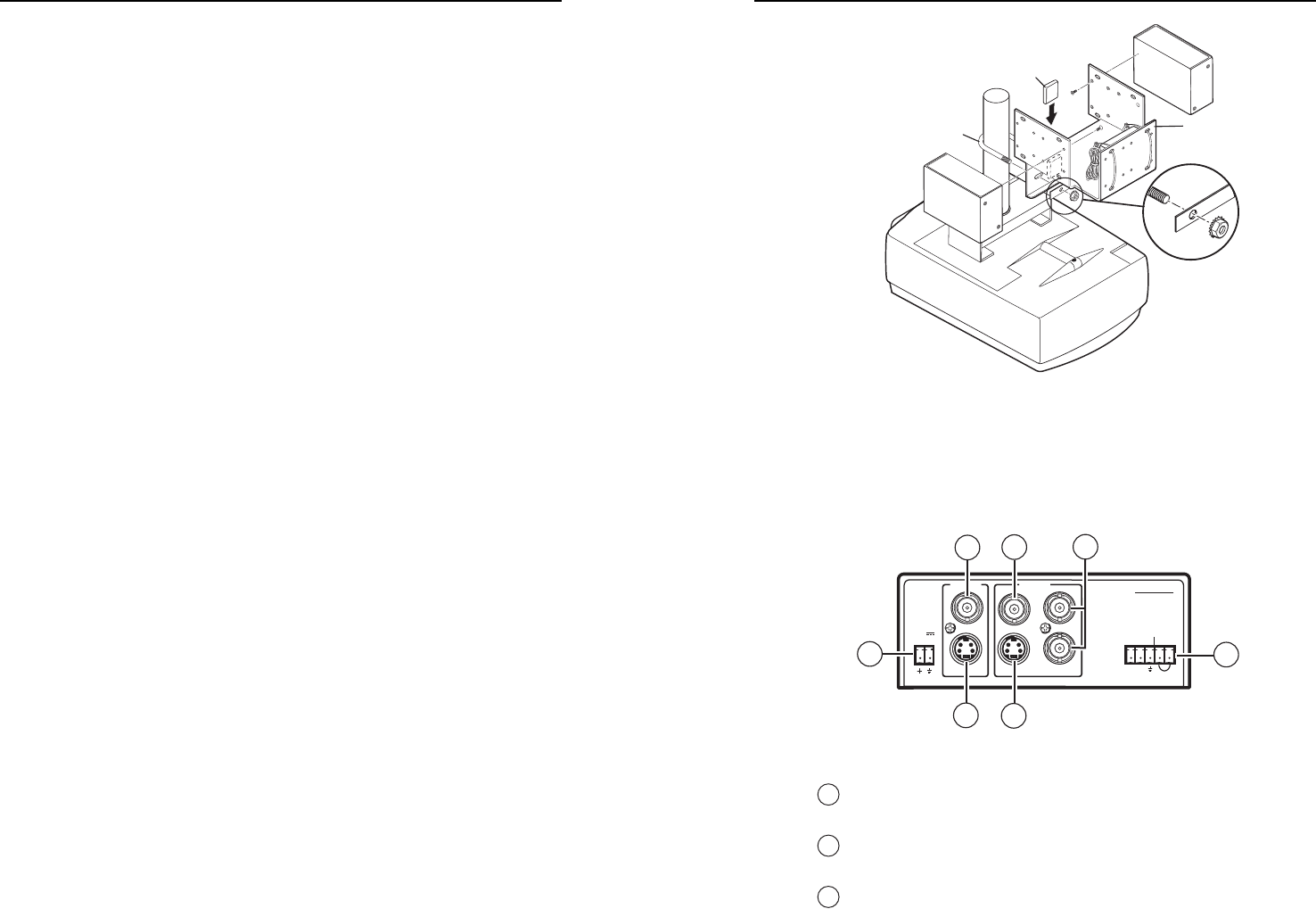
Multi Product
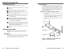
Projector Mounting Kit
U-Bolt
Rubber Pad
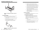
Figure 2-9 — Projector-mounting the YCS SW2 using
the PMK 300 Projector Mount Kit
Rear Panel Features
INPUTS
1Y
C
2
OUTPUT
POWER
YCS SW2
12V
0.3A MAX
CONTACT
12
AUTO -SW
VIDEO
S-VIDEO
7
5
3
2
4
6
1
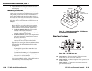
Figure 2-10 — YCS SW2 rear panel
1
Power connector — Plug the external 12 VDC power supply
into this 2-pin, 3.5 mm captive screw connector.
2
Input 1 connector — Connect a composite video input source to
this BNC connector.
3
Input 2 connector — Connect an S-video input source to this
4-pin mini-DIN connector.
11. If desired, choose one of the provided four sizes of self-
adhesive cover sheets, and apply it to the underside of the
mounting tray.
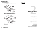
PMK 300 Projector Mount Kit
The PMK 300 Multi-Product Projector Mount Kit (#70-374-01)
mounts up to three quarter-rack width products to a projector
ceiling mount pole. The YCS SW2 can be mounted above the
display device with the front panel facing either down or up.
The quarter rack width plate can also be used to mount the YCS
external desktop power supply.
Follow these steps to projector-mount the YCS SW2 using the
PMK 300:
1. If necessary, remove the feet from the bottom of the YCS.
2. Mount the YCS to one of the bracket’s three mounting
plates. It can be vertically mounted facing either up or
down, whichever is most convenient. See fi gure 2-9.
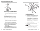
• On the side mounting plates, the YCS is typically
mounted on the outside of the bracket.
On the front mounting plate, the device is typically
mounted on the inside of the bracket.
• For the YCS SW2 unit, use two of the supplied 4-40 x
3/16 screws in opposite (diagonal) corners to secure
the device to the bracket.
For the YCS power supply, use the two included tie
wraps to strap the power supply to the bracket.
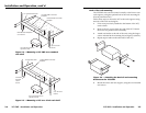
3. Place the U-bolt around the ceiling pole and insert the two
legs of the U-bolt through the slotted holes on the bracket’s
mounting plate, then through the round holes on the
backing brace.
• For a typical (1.5” to 2.0” diameter) pole — You can
use the supplied square U-bolt, which fi ts a typical
ceiling pole.
• For a smaller or larger pole — Locally obtain a square
U-bolt that fi ts your ceiling pole. The slotted holes on
the bracket can accomodate a square U-bolt for pole
sizes from 1.0” to 2.5” in diameter.
4. Secure the bracket to the U-bolt with the included hex
nuts, washers, and lock washers. Tighten the hex nuts just
enough that they can be loosened by hand.