


YCS SW2 • Installation and Operation
Installation and Operation, cont’d
2-12
YCS SW2 • Installation and Operation
2-13
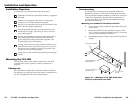
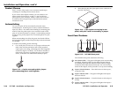
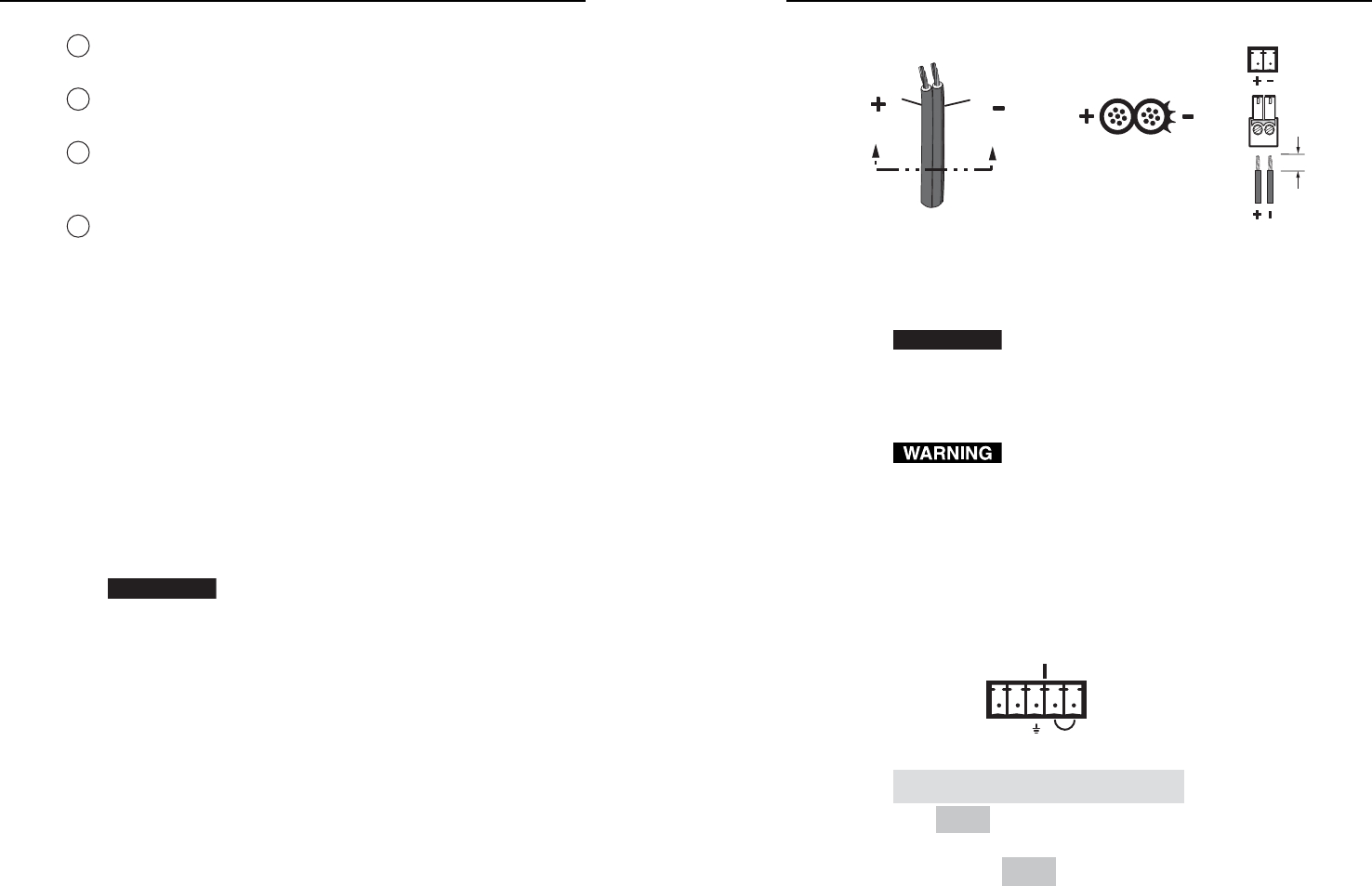
The fi gure below shows how to wire the connector.
Power Supply
Output Cord
Captive Screw
Connector
0.2” (5 mm)
SECTION A–A
Ridges
Smooth
AA
Figure 2-11 — Power connector wiring
CAUTION
Do not tin the stripped power supply leads before
attaching the captive screw plug to them. Tinned
wires are not as secure in the captive screw
connectors and can be easily pulled out. They may
also break after being bent several times.
The two power cord wires must be kept separate
while the power supply is plugged in. Remove
power before wiring.
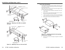
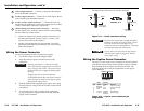
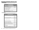
Wiring the Captive Screw Connector
The 5-pin, 3.5 mm captive screw connector is used for optional
push-button remote control of the YCS SW2, and/or to enable
autoswitching between inputs connected to the YCS. The
following fi gure shows the pin assignments for the captive
screw connector.
PIN
Auto-
switch
Contact
Closure
Function
1
—
In #1 Input #1 (contact)
Input #2 (contact)
2
—
3
4
In #2
5
Gnd
Gnd
Ground
12
CONTACT
AUTO-SW
Autoswitching
(1)
(2)
(3)
(4)
(5)
Autoswitching
—
—
To Pin 5
To Pin 4
Figure 2-12 — Captive screw connector pin
assignments
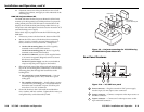
4
Video output connector — Connect a composite video display
device to this BNC connector.
5
S-video output connector — Connect an S-video display device
to this female 4-pin mini-DIN connector.
6
S-video Y and C output connectors — Connect the luma (Y)
and chroma (C) connectors of an S-video display device to these
Y and C female BNC connectors, respectively.
7
Autoswitching and contact closure connector — This 5-pin,
3.5 mm captive screw connector can be used for autoswitching
and for control by contact closure.
Connect an optional two-button contact closure device to
the three ports labeled “Contact” (pins 1, 2, and 3). (See
Contact closure, later in this chapter.)
Jumper-wire together the two ports labeled “Auto-SW”
(pins 4 and 5) to enable autoswitching. (See Autoswitching,
later in this chapter.)
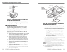
Wiring the Power Connector
To wire the connector for the external power supply,
1. Cut the DC output cord to the length needed.
2. Strip the jacket to expose 0.2 inches (5 mm) of the
conductors.
CAUTION
Exposing more than 0.2” (5 mm) of the copper
wires could allow the stripped wires to touch each
other, causing a short circuit. This could result in
the external DC power supply overheating and/or
burning.
Stripping the wires to expose less than the
recommended amount may cause them to slide out
of the connector too easily, even if they are tightly
pinched by the captive screws.
3. Slide the leads into the supplied 2-pin captive screw plug
and secure them, using an Extron Tweeker or other small
screwdriver.
4. To verify the power cord’s polarity before connecting
it, plug in the power supply with no load and check the
output with a voltmeter.
•
•