


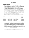
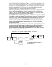
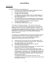
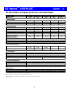
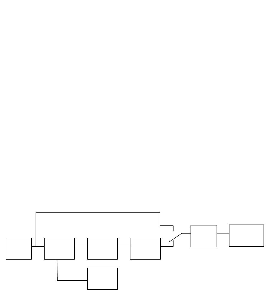
Refer to the simplified block diagram, Figure 1, for a system description. The
AC source is rectified and provides energy for the DC + Choppers and a float
charge to the optional standby Battery. These DC Choppers then supply the
power to operate the DC/AC Inverter. The inverter provides a new clean
sinewave output at the factory configured output frequency.
When configured with an optional battery bank and during a utility power-loss,
the AC rectification and battery charging capabilities of the UPS become
inactive. The fully-charged battery, however, supplies the necessary power
requirement to maintain the remaining system blocks.
The FALCON
®
ED on-line topology is unique to other on-line systems, in that, it
is designed to meet the needs of non-linear loads. Equipment, configured with
a switching power supply, is considered a non-linear load which can be very
abusive to most power conversion and protection equipment, and could
decrease its life-expectancy. The FALCON
®
ED unit is specially designed to
accept these loads and protect them efficiently with minimal of the output
waveform degradation.
For ED models configured with batteries, please refer again to the figure below,
you will notice a built-in safeguard. If the unit has not been configured as a
frequency converter, when it inadvertently experiences an extreme over
temperature situation that causes inverter malfunction, it will switch over to a
filtered emergency bypass line to insure
INPUT
FILTER
RECTIFIER
CHARGER
+ DC
CHOPPERS
DC/AC
INVERTER
OUTPUT
FILTER
COMPUTER
(LOAD)
STANDBY
BATTERY
EMERGENCY
BYPASS LINE
EMERGENCY
BYPASS
SWITCH
FIGURE 1: FALCON ED SERIES BLOCK DIAGRAM
3
Emergency bypass functions have been disabled
in all ED models configured for frequency
converter operation.